
For a short range radar level transmitter on a vessel where the liquid sits 100 mm to 1600 mm below the flange, the spec that decides everything is the blocking distance (also called dead band or near-range limit).
If the maximum level comes closer to the antenna than that distance, the reading is not valid. After that, check beam angle (higher frequencies such as 80 GHz give a narrower beam from a smaller antenna), mounting position, and how you scale 4-20 mA. On short ranges, a few tens of millimetres matter.
Who this is for: Instrument and process engineers fitting level measurement on day tanks, dosing tanks, small buffer vessels and sumps under 2 m tall. Operators working with cranes, material handling equipment, logistics, supply chain equipment, process autoamtion requirements, to detect objetcs automatically, over a distance.
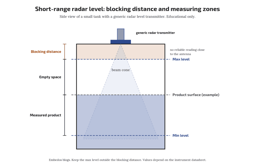
Blocking distance dominates short ranges
A short range radar transmitter measures time of flight of a microwave signal reflected from the surface. Close to the antenna, the transmitted signal and nozzle reflections mask the echo, so vendors state how close to the antenna the level may come.
For example, Endress+Hauser Technical Information TI01683F/00/EN/01.22 for the 80 GHz Micropilot FMR60B states that the range measures to the antenna tip and recommends ending the measuring range 10 mm before the tip (Endress+Hauser Micropilot FMR60B). Always read the near-range limit from your model’s own Technical Info.
Rule of thumb:
Maximum level must stay below the blocking distance plus a safety margin, measured from the antenna reference point stated in the manual (not always the flange face).
Worked example: (hypothetical figures, not from TI01683F or any one model): tank top flange to bottom 1700 mm. Assumed blocking distance 100 mm from the reference point.
Maximum level allowed = 1700 − 100 − 50 margin = 1550 mm of liquid.
If the overflow sits higher, raise the nozzle or choose a model with a shorter near zone.
What if the tank sometimes overfills into the blocking zone?
The reading can freeze or jump. Add an independent high-level switch for overfill protection; do not depend on the radar in its own blind zone.
Frequency and beam angle
Beam angle is narrower for higher frequency and larger antenna. 80 GHz instruments give a narrow beam from a small antenna, which helps on small tanks where walls, agitators and ladders are close.
For example, VEGA brochure 52552 for the 80 GHz VEGAPULS 64 mentions a beam angle of only 3° with an 80 mm antenna (DN 80 / 3″ flange); smaller antennas give wider beams, so check the figure for the antenna you order (VEGA brochure 52552, VEGAPULS 64).
Level probing radar use is regulated in Europe under ETSI EN 302 729 (ETSI). For India, confirm vendor WPC/DoT type approval for the instrument. Note that DoT notification G.S.R. 468(E) of 11 June 2026 delicenses 77 to 81 GHz for vehicle radar only; it does not cover tank level radar.
Mounting on small vessels
Keep the beam clear of walls, inlet streams and agitator blades.
Vendors usually advise mounting away from the centre (to avoid multiple reflections from a domed roof) and away from the inlet.
- Short nozzles: long or narrow nozzles add false echoes near the antenna, which effectively extends the dead zone. Follow the maker’s nozzle length and diameter limits.
- Foam and condensation: both weaken or scatter echoes. Ask the vendor about the product’s behaviour with your medium.
- Run a false echo map (mapping) with the tank empty or at low level during commissioning.
Should 4-20 mA represent level or distance?
Usually level from the tank bottom, scaled to the usable span.
Is 80 GHz better for small tanks?
Often, because a narrower beam from a small antenna avoids walls and internals. Check your medium and nozzle with the vendor.
4-20 mA scaling for short ranges
Decide whether 4-20 mA represents level (from the bottom) or distance (from the antenna). Most plants want level.
- Set empty (4 mA) at the bottom reference and full (20 mA) at maximum usable level, not at the flange.
- Level = (mA − 4) ÷ 16 × span. With a 0-1500 mm span, 12 mA = 750 mm.
- On a 1.5 m span, 1 mm = about 0.011 mA. Check that your analog input resolution and the transmitter’s stated accuracy are adequate. The 4-20 mA signal range is defined in IEC 60381-1 .
- For volume on a horizontal or dished tank, apply a strapping table in the PLC or display, not a straight line.
Check your own numbers with the free Embedos | – 4-20 mA loop scaling calculator.
Quick selection checklist
| Check | Question |
|---|---|
| Blocking distance | Is max level below it, with margin? |
| Reference point | Where does the manual measure from? |
| Frequency and beam | Clear of walls and internals? |
| Nozzle | Within maker’s length and diameter limits? |
| Medium | Foam, vapour, condensation, low dielectric? |
| Output | 4-20 mA scaled to level, fault current set |
| Overfill | Separate high-level switch fitted? |
Do I still need a high-level switch?
Yes, for independent overfill protection.
Showing level and alarms
Once the short range radar transmitter gives a clean 4-20 mA signal, it can be displayed, alarmed and logged.
Our Embedos Em Bose (EB) Series _ tank-level solution displays level and alarms from a third-party sensor
The live page primary path is a sensor at the tank bottom; a distance or level sensor can also feed the display ( relative density calculation then will be different depending on the type of sensor mounting).
What is blocking distance on a radar level sensor?
The zone near the antenna where the instrument cannot measure. Maximum level must stay outside it.
Next step! Send us a Mail
Send your tank drawing, nozzle size and level range, and we will help you check the fit.
Email: team@embedos.io
Help Us Help You Leverage The Power Of Industrial Automation & Industrial IoT – IIoT.