
Vibration Transmitter 4-20mA 0-25 mm/s: Buyer Guide

Direct answer: a vibration transmitter 4-20mA 0-25 mm/s gives one number per point: overall RMS vibration velocity on the bearing housing, scaled so 4 mA = 0 mm/s and 20 mA = 25 mm/s.

That range suits most general-purpose motors, fans and pumps, because typical alert and trip levels in the ISO 20816 framework sit well inside 25 mm/s. When buying one, fix five things on the datasheet: measured quantity (RMS velocity), range, frequency band, mounting method, and how you will set alarm limits.

This guide is educational; it does not describe an Embedos product.

Who this is for: maintenance and instrumentation engineers writing a spec or purchase request for loop-powered vibration transmitters on motors, fans, blowers and pumps.

Tell us what you need on site

Need this on your plant? Tell us your requirement

If you have not yet decided between 4-20 mA and RS-485 Modbus, read 4-20mA vs RS485 vibration sensor for motor monitoring first. 
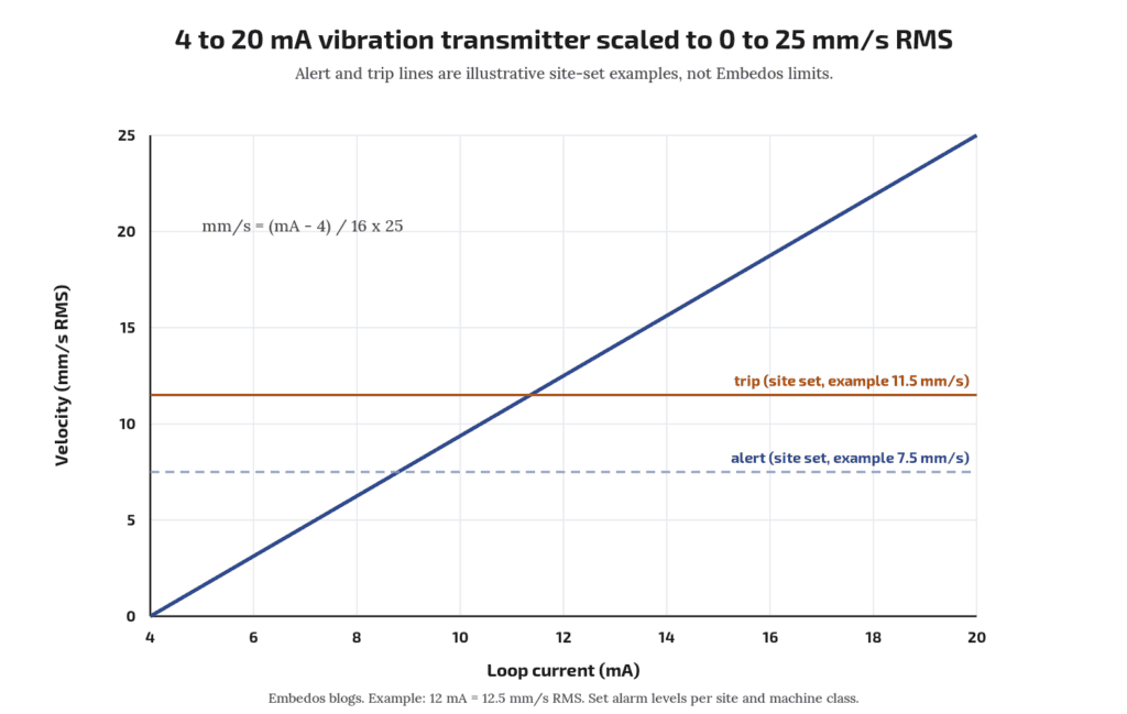
Embedos blogs embedos-blogs diagram: 4 to 20 mA line mapped to 0 to 25 mm/s RMS velocity with example alert and trip lines

What the transmitter measures

The usual trend value for rotating machines is broadband RMS vibration velocity in mm/s, measured on non-rotating parts such as bearing housings. ISO 20816-1 sets out general guidelines for measuring and evaluating machine vibration on these parts (ISO 20816-1). Velocity is used because, over the middle frequency range where imbalance, misalignment and looseness show up, it tracks vibration severity reasonably evenly.

A 4-20 mA transmitter contains an accelerometer, integrates the signal to velocity, filters it to a band, calculates RMS, and drives the loop. The 4 to 20 mA live-zero range is standardised in IEC 60381-1 (IEC webstore).

Check on the datasheet: RMS, not peak or peak-to-peak. Some transmitters offer “peak” velocity or “equivalent peak” (RMS × √2). Mixing them gives a 41% error when you compare against ISO-style limits.

Why 0-25 mm/s is the common range

Two reasons:

  1. Resolution where it matters. On a 0-25 mm/s range, 1 mm/s is 0.64 mA (16 mA ÷ 25). Healthy machines often run at a few mm/s, so a wider range such as 0-50 mm/s halves the current change per mm/s and makes small trends harder to see on a 12-bit input.
  2. Headroom above trip. Set alert and trip levels by evaluating against ISO 20816-3 zone boundaries for the machine group and foundation (ISO 20816-3). A 25 mm/s top leaves room above trip so the signal does not saturate during a fault.

Pick 0-50 mm/s or wider only for machines that run rough by design (some crushers, vibrating screens) where the maker states higher normal levels.

Scaling: velocity = (mA − 4) ÷ 16 × 25. At 8 mA, velocity = 4 ÷ 16 × 25 = 6.25 mm/s. Check your own with the 4-20 mA loop scaling calculator.

What should the input read when the wire breaks?

Below 4 mA, often near 0 mA. Set the receiver to flag a current below the NE 43 failure range (about 3.6 mA on most transmitters; check the manual) as a fault, in line with NAMUR NE 43 (NAMUR). Check whether your transmitter supports NE 43 signalling.

Frequency band

The broadband measurement band depends on machine speed per ISO 20816; read the band for your machine from the relevant part (ISO 20816-1).

Buyer checks:

  • Does the datasheet state the band and does it suit your machine speed per ISO 20816? If not, ask.
  • Slow machines: a fan at 300 rpm runs at 5 Hz. A transmitter whose lower cut-off sits near or above 5 Hz will miss most of its 1× vibration. Choose a transmitter with a lower cut-off well below running speed.
  • Bearing defects: early rolling bearing faults show at higher frequencies and often in acceleration, not velocity. A 0-25 mm/s velocity transmitter is a general health trend, not a bearing diagnostic tool.
Can one 4-20 mA transmitter catch bearing faults early?

Not reliably. It gives overall velocity. For early bearing faults, look at acceleration or envelope values, usually from an RS-485 or portable analyser. See ENQ-007 for the trade-off.

Mounting

Mounting changes the reading more than most spec items.

  • Location: on the bearing housing, close to the load zone, in the direction you want to watch (horizontal on most horizontal machines, since stiffness is usually lowest there).
  • Method: a stud on a spot-faced flat surface gives the best frequency response. Adhesive mounting pads are a common second choice. Magnets are for surveys. Vendor application notes show how the usable upper frequency drops as mounting gets less rigid; check the accelerometer maker’s mounting manual for the response of each method.
  • Thread: confirm thread size (often 1/4-28 UNF or M8) and whether an adaptor is supplied.
  • Cable: armoured or screened twisted pair, screen grounded at one end per your plant practice. On VFD-driven motors keep the run away from motor power cables.
  • Enclosure: state the IP rating needed. Degrees of protection are defined in IEC 60529 (IEC webstore). For hosed-down areas ask for IP66 or IP67 and check the cable gland too.
  • Hazardous areas: if the motor is in a classified zone, you need a certified transmitter and the right barrier. Do not substitute.

Download the Free “Vibration Transmitter 4-20mA 0-25 mm/s Checklist”

Enter your email and the form emails you the copy link to the Google Sheet.


Alarm limits: how to frame them

ISO 20816 evaluates vibration in two ways: absolute magnitude against zones, and change from a known baseline. Use both.

  1. Classify the machine by type, power and foundation (rigid or flexible) as the relevant ISO 20816 part requires.
  2. Read the zone boundaries from that part for your class. Zone A is new machines, B is acceptable for long-term running, C is limited running, D is damaging.
  3. Set alert near the B/C boundary, or at baseline plus an agreed step if the machine normally runs well below it.
  4. Set trip no higher than the C/D boundary, and only if your protection philosophy allows a trip from this signal.
  5. Add a delay of a few seconds to ride through start-up transients.

Alert and trip values are site decisions. Write down which ISO part and table you used so the next engineer can check it.

Should a vibration transmitter trip the motor directly?

Some plants wire it to a PLC trip; others alarm only. Follow your protection philosophy and get it reviewed. Never rely on a polled network value as the only trip path without review.

Spec sheet checklist

Item What to write
Measured quantity RMS velocity, mm/s
Range 0-25 mm/s (state if different, with reason)
Output 4-20 mA, 2-wire loop powered, NE 43 fault signalling if available
Frequency band Per machine speed (ISO 20816); lower cut-off for slow machines
Supply e.g. 24 V DC nominal; check minimum loop voltage with your input load
Mounting Stud, thread size, spot-face required
Enclosure IP rating per IEC 60529; cable entry type
Temperature Ambient and surface temperature of the bearing housing
Approvals Hazardous area certification if needed
Documents Datasheet, calibration certificate, mounting guide

Where the data goes

The 4-20 mA loop lands on a PLC analog input or a gateway. From there it can be trended and alarmed. Embedos has interfaced third-party vibration sensors with Embedos Edge, our platform of products, solutions, dashboards, insights and services.

A vibration monitoring software case records a historical EmView-named desktop deployment that logged spindle vibration over OPC UA; that page is a case note, not the current EmView product definition.

Today, readings can be shown on EmView monitoring screens (sign in at emcommandview.embedos.io). The transmitter itself is chosen from your preferred instrument vendor.

FAQ

Why 0-25 mm/s and not 0-50 mm/s?

Better resolution at normal running levels, while still above typical trip levels for general machines. Use wider ranges only where the maker states higher normal vibration.

RMS or peak velocity?

RMS, to compare against ISO 20816 framing. Peak is about 1.41 × RMS for a pure sine.

What frequency band do I need?

The band depends on machine speed per ISO 20816; slow machines need a lower cut-off. Confirm against the ISO part you use.

Stud or magnet mounting?

Stud for permanent installs. Magnets shift and reduce high-frequency response.

4-20 mA or RS-485?

4-20 mA for one value per point into existing analog I/O; RS-485 for multiple values per sensor on one cable.

Next step

Send your motor list (power, speed, foundation type) and we will help you frame the transmitter spec and alarm limits.

Email: team@embedos.io

Help Us Help You Leverage The Power Of Industrial Automation & Industrial IoT – IIoT.

Flow Meter Pulse Output vs 4-20mA: Which to Use and When

Is pulse output more accurate than 4-20 mA?

For totals, usually yes, because pulses are counted rather than integrated. For live rate, both can work; accuracy then depends on the meter and input.


Direct answer: use the pulse output when you need an accurate total (litres, m³ consumed per shift or batch), and use 4-20 mA when you need the live flow rate for control, trends or alarms.

Pulses are counted, so a total built from them has no integration error beyond the meter’s own K-factor. A total built by integrating a 4-20 mA signal accumulates the small offset, scaling and sampling errors of the analog chain. Many plants wire both: pulses to a counter or totaliser, 4-20 mA to the PLC loop, and a separate flow switch contact for a no flow alarm.

Who this is for: instrumentation and utility engineers wiring water, cooling water, fuel oil, chemical dosing or effluent meters into a PLC, panel totaliser or energy monitoring system.

Do I need a high speed counter input?

If pulse frequency at max flow exceeds the input’s rated counting frequency, or pulse width is shorter than its filter time, yes.

Can I calculate total flow from 4-20 mA?

Yes, by integrating rate over time, but offset, span and sampling errors accumulate. Use a low flow cut-off and check against a pulse or manual reading.

Tell us what you need on site

Need this on your plant? Tell us your requirement

PNP or NPN, which should I choose?

Match the PLC input. Sinking PLC inputs pair with PNP outputs; sourcing inputs, or a pull-up resistor, pair with NPN.

What is a K-factor on a flow meter?

The number of pulses the meter sends per unit volume, such as 50 pulses per litre, from its calibration certificate.

The two signals in one line each

  • Pulse (frequency) output: one pulse per fixed volume. Pulse frequency is proportional to flow rate; pulse count is proportional to total volume.
  • 4-20 mA output: a current that maps the flow range linearly, 4 mA at zero (or range low) and 20 mA at full scale. The live-zero 4 to 20 mA range is standardised in IEC 60381-1:1982 (IEC webstore).

K-factor: turning pulses into litres

The K-factor is pulses per unit volume, given on the meter’s calibration certificate. A KEP application note puts it simply: the certificate gives the average K-factor, for example 200 pulses per US gallon or 150 pulses per litre, and that number is entered into the totaliser (KEP, Calculating and Using K-Factors).

Worked example (illustrative): a cooling water meter has K = 50 pulses per litre.

  • Total: 1,250,000 pulses counted over a shift ÷ 50 = 25,000 L = 25 m³.
  • Rate: pulse frequency 125 Hz ÷ 50 = 2.5 L/s = 9 m³/h.

Field check of K, as Seametrics describes: reset the total, set K = 1, run a known volume into a container, read the pulse count, divide pulses by volume (Seametrics field calibration bulletin). For example 500 pulses into a 10 L can gives K = 50 pulses/L.

Some meters, such as turbine meters, have a K-factor that varies across the flow range. Meter manuals state linearity; one turbine sensor manual lists ±3% of reading linearity and ±0.5% repeatability (GF Signet 2100 manual). If that matters, use a totaliser with multi-point K-factors.

4-20 mA scaling

Rate = range low + (mA − 4) ÷ 16 × (range high − range low).

Example: 0 to 50 m³/h range, signal 12 mA. Rate = (12 − 4) ÷ 16 × 50 = 25 m³/h. You can check your own numbers with our 4-20 mA loop scaling calculator.

Why integrating 4-20 mA drifts

To get a total from 4-20 mA, the PLC samples the rate and adds rate × time each scan. Errors add up:

  1. Zero offset: a meter at true zero sending 4.05 mA reads 0.05 ÷ 16 × 50 = 0.16 m³/h. Over 24 h that is about 3.75 m³ of “flow” that never happened. Use a low flow cut-off.
  2. Span error: analog input and transmitter tolerances scale every reading.
  3. Resolution: an input with limited counts over 4 to 20 mA quantises the rate.
  4. Sampling: if flow pulses or changes fast between samples, the sum misses it.
  5. Restart loss: a PLC restart without retained memory can reset the total.

Pulses avoid points 1 to 4 because each pulse is a counted, fixed volume. They still need retained counters and protection against missed pulses.

PNP, NPN and open collector outputs

Pulse outputs are typically open collector (NPN, sinking), PNP (sourcing), or a passive contact (reed). The input must match:

  • NPN / open collector: the output pulls the line to 0 V. The input must be a sourcing type (it supplies current that the output sinks), or you add a pull-up resistor to supply. Check the meter’s maximum switching current and voltage.
  • PNP: the output drives the line to supply voltage. Use a sinking type PLC input (current flows from the output into the input).
  • Reed or mechanical contact: low frequency only, and contact bounce needs input filtering.

IEC 61131-2:2017 defines Type 1, Type 2 and Type 3 24 V DC digital inputs, each with its own on and off voltage and current limits; read the exact thresholds from your PLC input datasheet (IEC webstore). A pulse output has to cross both thresholds cleanly.

Maximum frequency

At full flow, pulse frequency = K × max flow. Example: K = 50 pulses/L, max flow 5 L/s gives 250 Hz. Check three limits:

  • The meter’s maximum output frequency and minimum pulse width
  • The input’s maximum counting frequency (ordinary PLC digital inputs are filtered; a high speed counter input may be needed)
  • The input filter time, which must be shorter than the pulse width

If frequency is too high, many meters let you set a pulse scaler (one pulse per 10 L). Each pulse then represents more volume, which lowers total resolution but stays accurate.

Download the Free “Flow Signal Wiring and Totaliser Checklist”

Enter your email and you will receive a Sheet, right in your inbox that can be customized by yourself. 


Why add a separate flow switch?

So a no flow condition trips equipment directly, independent of the PLC analog chain.

Cable length and noise

  • 4-20 mA is a current loop, so voltage drop along the cable does not change the reading as long as the loop supply covers transmitter minimum voltage plus load and cable resistance. That makes it tolerant of long runs. Check the loop voltage budget on the transmitter datasheet.
  • Pulse signals are voltage edges. Long cables add capacitance that rounds edges and can pick up spikes from VFD and motor cables, causing false counts. Use shielded cable, earth the shield at one end, keep it away from power cables, and use input filtering suited to the max frequency.
  • In a steel plant or rolling mill bay with large drives, route signal cables in separate trays from power. In process plants with long field runs, 4-20 mA for rate is often the easier signal to keep clean.

Use both, plus a flow switch

A common pattern in Indian utility and process plants:

Need Signal Destination
Shift or batch total, billing, water audit Pulse Counter input or panel totaliser
Live rate, PID loop, trends 4-20 mA PLC analog input
No flow or low flow alarm (pump dry run, cooling water loss) Flow switch contact Hardwired interlock and PLC DI

The flow switch is a separate discrete device (or a configurable meter relay output) so that a loss of cooling water trips a furnace or compressor even if the PLC analog chain fails. Wire it fail safe: contact closed when flow is healthy.

If the meter supports a fieldbus or Modbus output, it may give rate and total over one cable. That is outside this guide’s scope.

If you want a panel display for this, the Em Bose EB series has digital inputs for pulse signals and analog inputs for 4-20 mA, and a Flow Totalizer application. Check the live product page for input ratings against the maximum pulse frequency you worked out above.

Next step

Send your meter datasheet, flow range and what you need (total, rate, alarm) to
Email: team@embedos.io

Also download the free flow signal wiring and totaliser checklist mentioned above. 

Help Us Help You Leverage The Power Of Industrial Automation & Industrial IoT – IIoT.

PT100 to 4-20mA Transmitter or Direct RTD Input?

Wire a PT100 directly to an RTD input when the cable is short and the receiver has a proper PT100 direct input with 3-wire or 4-wire lead compensation.

Use a PT100 to 4-20mA transmitter, usually a head mounted temperature transmitter inside the sensor’s connection head, when the run is long, the area is electrically noisy, or the receiver only has 4-20 mA inputs.

The transmitter converts the small resistance change into a current that cable resistance does not affect, at the cost of one more device to buy, configure and calibrate.

Who this is for: plant, utility and maintenance engineers adding RTD temperature monitoring to tanks, bearings, ovens, cold rooms or process lines, and integrators choosing between RTD and 4-20 mA input cards.

Tell us what you need on site

Need this on your plant? Tell us your requirement

What a PT100 gives you, and why wiring matters

A PT100 is a platinum resistance thermometer with 100 ohms at 0 °C. Its resistance versus temperature relationship and tolerance classes are defined in IEC 60751:2022 (scope and edition). The common -200 °C to +850 °C range and the 0.003851 per °C coefficient are described in TI’s RTD measurement guide SBAA275A. In round numbers that is about 0.385 ohm per °C near room temperature.

That small slope is the whole problem. Every ohm of copper lead resistance that gets counted as sensor resistance reads as roughly 2.6 °C of error. TI’s A Basic Guide to RTD Measurements works through how 2-wire, 3-wire and 4-wire connections handle that lead resistance.

Is PT1000 better for long cables?

A PT1000 has ten times the resistance and ten times the slope, so the same lead resistance causes about one tenth of the error in a 2-wire connection. It still needs a receiver that supports PT1000 and it does not remove noise pickup on long runs.

PT100 3 wire vs 4 wire (and 2 wire)

Connection How leads are handled Lead error Typical use
2-wire Both lead resistances add to the reading Highest, grows with length Very short leads, or a head transmitter mounted at the sensor
3-wire Receiver measures and subtracts lead resistance, assuming leads are matched Small if leads are equal The common industrial default
4-wire Separate current and sense pairs, sense leads carry almost no current Effectively removed Lab, calibration, high-accuracy points

TI’s guide notes that 3-wire compensation assumes matched lead resistances, and that 4-wire connections remove lead resistance error because the sense leads carry no excitation current. In practice, a 3-wire run with mismatched terminals, corroded joints or mixed cable cores loses part of its compensation.

Can I run a 3-wire PT100 on a 2-core plus shield cable?

No, the shield is not a matched conductor. Use three matched cores so the compensation works as intended.

How long can a direct PT100 run be?

There is no single number. It depends on the cable resistance, whether leads stay matched, the noise environment and the receiver’s input design. Many receiver datasheets state a maximum lead resistance; work back from that to cable length. If the run is long and passes VFDs or heavy power cables, a transmitter at the sensor is the safer choice.

embedos-blogs-3-wire-pt100-to-4-20ma-transmitter-embedos-rtd: 3 wire PT100 sensor showing the three lead wires used for lead compensation

PT100 to 4-20mA transmitter: what changes

A head mounted transmitter sits in the sensor’s connection head (or a DIN rail transmitter sits in a nearby junction box) and does the RTD measurement right next to the element. The cable back to the panel then carries a temperature transmitter 4-20mA signal over two wires. Loop current is the same throughout the loop, so cable resistance does not change the reading as long as the loop supply has enough voltage, as explained in TI’s basics of 4-20 mA current loop transmitters. A broken wire drops the loop to 0 mA, below the 4 mA live zero, so the receiver can flag it.

Point Direct RTD input Head mounted 4-20 mA transmitter
Cable 3 or 4 matched cores per point 2 cores per point
Cable length sensitivity Lead resistance and matching matter Mainly loop voltage budget
Noise Millivolt level signal, more exposed Current signal, less affected
Receiver needed RTD input card or module Any 4-20 mA input
Wire break detection Depends on receiver Below 4 mA, visible on any input
Extra items None Transmitter, configuration, loop supply
Calibration Sensor plus receiver Sensor plus transmitter plus receiver
Range Set in the receiver Set in the transmitter (e.g. 0 to 150 °C)
Does the transmitter make the measurement more accurate?

Not automatically. It removes long-cable lead error and reduces noise, but it adds its own accuracy and drift figures, plus the receiver’s 4-20 mA input error. Add the sensor class, transmitter accuracy and input accuracy together when you compare.

Do I still need 3-wire between the PT100 and a head transmitter?

Inside the head the leads are short, so 2-wire error is small, but most head transmitters accept 3-wire or 4-wire and it costs nothing to use it. Follow the transmitter’s wiring diagram.

Cost and maintenance view

A direct RTD input saves the transmitter cost and one configuration step, which suits short runs inside a panel or skid. A transmitter adds hardware cost per point but uses cheaper 2-core cable and any 4-20 mA input, and the 4-20 mA signal is easy to check with a loop calibrator.

On sites with many existing 4-20 mA inputs and long runs, the transmitter route is usually less trouble over the life of the plant. For sensors bonded to earthed metal in noisy areas, choose an isolated transmitter.

Checklist

  • Note cable length and route for each point, and whether it passes VFD or power cables.
  • Check what the receiver accepts: PT100 direct, PT1000, or 4-20 mA only.
  • For direct wiring, use 3 or 4 matched cores and check the receiver’s maximum lead resistance.
  • For transmitters, set the range to fit the process with headroom, and check the loop voltage budget.
  • Decide whether the transmitter needs isolation.
  • Specify the sensor tolerance class to IEC 60751.
  • Plan calibration of sensor and loop together.

Where Embedos fits

Embedos Edge accepts 4-20 mA and 0-10 V DC analogue inputs on devices in the platform (for example Edison or Maxwell). The confirmed path for PT100 points today is: PT100, head mounted or DIN rail 4-20 mA transmitter, then an Edge analogue input scaled to °C. Edge then sends readings over MQTT or HTTPS, keeps data with data buffering during network outages, gives remote visibility of device health and connection status, and can raise threshold alerts by SMS, email or call.

Where temperature already sits in a controller or meter, Edge can read it over RS-485 Modbus RTU or Modbus TCP instead.

The Turing series is the temperature-specialist (Thermocouple / RTD expansion).  Can read RTD or Thermocouple Sensor Inputs directly, log data, and transmit data over MQTT, HTTP with or without TLS, over 4G Sim Card or Wi – Fi, SMS, email or call, directly. 

Next step. Drop a Mail!

The Embedos Turing (ET) series is the temperature-specialist.

Thermocouple / RTD Data Logger /  Gateway.

Email: team@embedos.io

Help Us Help You Leverage The Power Of Industrial Automation & Industrial IoT – IIoT.

4G vs 5G Industrial Router: Which Suits Your Plant in India

For PLC and SCADA telemetry (tag values, alarms, remote diagnostics) a 4G LTE industrial router with dual SIM failover is usually enough, because the data is small and LTE coverage is wider.

Choose 5G when you have a measured need for high bandwidth (several camera streams, large file transfers) or lower latency, and you have tested 5G signal at the exact panel location on more than one operator.

Whatever you buy for use in India, check its TEC MTCTE certification status.

Who this is for: plant engineers and IT/OT teams choosing a cellular router for remote monitoring of PLCs, SCADA nodes, pump stations, DG sets or solar sites.

What is dual SIM failover?

The router switches to a second operator’s SIM when the first link fails, keeping telemetry online.

Tell us what you need on site

Need this on your plant? Tell us your requirement

Can I run PLC control over a cellular link?

Use it for supervision and data. Keep control and safety logic local in the PLC.

Start with the data, not the radio

Estimate what you actually send. A worked example (illustrative):

  • 300 tags, each a 4 byte value plus about 50 bytes of protocol overhead, sent every 10 s
  • 300 × 54 bytes = 16.2 kB per update, 8,640 updates per day
  • About 140 MB per day, roughly 4.2 GB per month, before compression or report by exception

Even this generous case is a small, steady stream, well within LTE uplink capability. Report by exception (send only on change, as MQTT and many SCADA protocols support) can cut it further.

One 1080p stream, by contrast, typically needs several Mbit/s continuously (the YouTube encoding guide recommends 8 Mbit/s for 1080p at 30 fps; H.265 CCTV streams are often lower, so check the camera) (YouTube recommended upload encoding settings).

That is where bandwidth starts to matter.

Measure your own: most routers show data counters. Run a pilot for a week and look at the monthly total and peak.

What 4G gives you

  • Coverage: LTE networks in India are much wider than 5G, especially in industrial estates outside city centres. Check operator coverage maps, then test at site.
  • Bandwidth: LTE category (Cat 1, Cat 4, Cat 6 and above) sets peak rates; for telemetry even Cat 1 is often enough. Categories are defined by 3GPP in TS 36.306 (3GPP specifications).
  • Power and heat: 4G modules generally draw less than 5G modules, which helps in sealed panels and solar powered sites. Compare datasheet figures for the exact models.
  • Cost: 4G routers and plans are generally cheaper. We do not quote prices here.

What 5G adds

5G NR is specified by 3GPP from Release 15 onward (3GPP Release 15). For a plant router it can add:

  • Higher uplink and downlink throughput, useful for video, large log uploads or remote desktop to many HMIs
  • Lower air interface latency, which helps interactive remote work. End to end latency over public networks still depends on the core network and internet path
  • Release 17 introduced reduced capability (RedCap) devices for mid range IoT (3GPP Release 17); check operator support before relying on it

What it does not do: make a closed loop control link over a public network safe. Keep control in the PLC; use cellular for supervision and data.

Most 5G routers fall back to 4G when 5G is not available. Confirm the fallback bands too.

Coverage is the deciding factor

Plants are hard RF places: steel sheds, concrete, panels inside panels. Before you buy:

  1. Use a phone or a test router at the panel location, not at the gate.
  2. Record signal values (RSRP, RSRQ, SINR) for each operator, for 4G and 5G. These are defined in 3GPP TS 36.214 for LTE and TS 38.215 for NR.
  3. Test at different times of day.
  4. If signal is weak inside, plan an external antenna on the roof with low loss cable. Antenna gain does not fix a dead site.

Check which bands each operator uses in your area and that the router supports them. India’s spectrum assignments are published by DoT (Department of Telecommunications).

Does an external antenna help?

Yes, when signal inside the panel or shed is weak but usable outside. It cannot create coverage where none exists.

Choosing a router for remote monitoring?

Tell us your tag count, update rate and site location, and we will help you size the link. Email the Embedos team

When is 5G worth it for a plant?

When you have measured bandwidth or latency needs, such as multiple camera streams, and verified 5G coverage at the install point.

Is 4G enough for SCADA?

For tag data and alarms, usually yes. Estimate data per month and test signal at the panel.

Dual SIM failover

For telemetry, reliability usually matters more than speed. Dual SIM lets the router switch to a second operator when the first fails. Ask:

  • Is it dual SIM single standby (one active at a time, switch on failure) or dual modem (both active)? Single standby is common and cheaper; switching takes time.
  • What triggers failover: loss of registration only, or a failed ping to a set host? Ping based checks catch more real failures.
  • Does it fail back to the primary SIM, and when?
  • Does the VPN reconnect automatically after a switch?

Pair it with local buffering at the gateway or PLC so data during an outage is sent later, not lost.

Security basics

Whatever the radio, follow the same rules as any remote access to control systems:

  • No open ports from the internet to PLCs or HMIs. Use a VPN or an outbound only broker connection.
  • Private APN from the operator if available.
  • Change default passwords, keep firmware updated, turn off unused services.
  • Log remote sessions.

CISA’s primary mitigations for operational technology say to remove OT connections to the public internet and, where remote access is needed, use a private network or VPN with phishing-resistant multi-factor authentication (CISA, Primary Mitigations for OT). The IEC 62443 series is the reference for zones and conduits (ISA/IEC 62443).

India buyer check: TEC MTCTE

Under the Indian Telegraph (Amendment) Rules 2017, the Telecommunication Engineering Centre (TEC) runs the Mandatory Testing and Certification of Telecom Equipment (MTCTE) scheme.

The TEC notice dated 1 July 2024 (Annexure-I) lists Routers under Phase IV, mandatory from 1 August 2024, and IoT Gateway under Phase III, mandatory from 1 January 2024.

There is no separate cellular router category, so ask the seller which category their model is certified under (TEC MTCTE notice). Ask the seller for the MTCTE certificate number for the exact model and check it on the TEC portal (tec.gov.in).

Also ask whether a WPC Equipment Type Approval (ETA) applies to the radio in that model (DoT).

Side by side

Factor 4G LTE router 5G router
Typical fit Telemetry, alarms, remote diagnostics Video, large transfers, low latency remote work
Coverage in industrial areas Wider Growing; test at site
Power and heat Lower, generally Higher, generally; check datasheet
Cost Lower Higher
Fallback Check whether any 3G/2G fallback exists with your operator Falls back to 4G
Must check Bands, dual SIM, MTCTE Bands, measured 5G signal, MTCTE

If your need is small Modbus telemetry over 4G rather than a general purpose router, see our 4G Ethernet Modbus gateway with Wi-Fi page for its 4G SIM, Wi-Fi and Ethernet options. 

Do industrial routers need TEC certification in India?

Telecom equipment in notified categories needs MTCTE certification. Ask for the certificate for the exact model and verify on the TEC portal.

Next step

Send your site location, tag count and whether video is in scope.

We will help you pick the link and the test plan.
Email: team@embedos.io

Help Us Help You Leverage The Power Of Industrial Automation & Industrial IoT – IIoT.

Modbus Register Map: How Do You Read It and Decode 32-bit Values (ABCD, CDAB, BADC, DCBA)?

Direct answer: a Modbus register map tells you, for every value, its data table (and so its function code), address, data type, scale and unit. Send the address as a 0-based offset (holding register 40001 goes out as address 0), read each 32-bit value as two consecutive registers, then try the byte orders ABCD, CDAB, BADC and DCBA until the number lands in the expected range. Our free Modbus register interpreter shows all four side by side.

Who this is for: plant and commissioning engineers connecting an energy meter, VFD or sensor to a PLC, SCADA or gateway, with the vendor’s register map in one hand and strange numbers on screen.

What you’ll be able to do after reading:

  • Pick the right function code for each row of a map.
  • Convert a 4xxxx register number into the address your master sends.
  • Decode 16-bit, 32-bit and float values and find their byte order from one known reading.
  • Apply scaling and units, and commission a new device with a checklist.

What does a Modbus register map contain?

A register map binds a device’s internal values to Modbus addresses. The Modbus Application Protocol Specification V1.1b3 calls this mapping “totally vendor device specific”, so two meters measuring the same voltage can look nothing alike on the wire. A usable map gives, for each value:

  • Parameter name and unit, such as line voltage in V.
  • Data table or function code.
  • Address, as a 0-based offset or a 1-based number such as 40001.
  • Data type and number of registers.
  • Word order for 32-bit values, and any scale factor.
  • Read only or writable.

If a column is missing, ask the vendor before you start polling.

Embedos blogs embedos-blogs: PLC rack with I/O modules and labelled wiring in an industrial control panel, the kind of Modbus master that reads a register map

Which function code reads which data table?

The table follows section 4.3 and the function code chapters of the application protocol spec. The 0x, 1x, 3x and 4x prefixes come from the older Modicon Modbus Protocol Reference Guide PI-MBUS-300 Rev. J, which many manuals still follow.

Data table Object Access Read function code Write function code Legacy reference
Coils 1 bit Read and write 01 05 (single), 15 (multiple) 0xxxx
Discrete inputs 1 bit Read only 02 None 1xxxx
Input registers 16-bit word Read only 04 None 3xxxx
Holding registers 16-bit word Read and write 03 06 (single), 16 (multiple) 4xxxx

One 03 or 04 request reads up to 125 registers; 01 or 02 up to 2000 bits. The spec lets devices overlay tables, so use the function code the map names.

Why is my reading off by one register?

The spec numbers elements in the data model from 1 to n but addresses them in the request from 0 to 65535, so a value numbered X is sent as address X minus 1. Its own example reads registers 108 to 110 with a starting address of 00 6B hex, which is 107.

The Modicon guide says the same thing in 4xxxx language: holding register 40001 is sent as address 0000, and 40108 as 006B hex. The leading 4 is not sent at all, because function code 03 already says “holding register”.

  1. A five-digit map number starting with 3 or 4 is a register number: subtract 30001 or 40001 to get the offset.
  2. Check your master. Some drivers take the register number and subtract 1 themselves; others want the offset. The driver manual says which.
  3. Prove it with a value shown on the device display. If it only looks right after shifting one register, you are off by one.

On 32-bit values this is easy to miss: you join halves of two different values and get a number that is wrong but not absurd.

Which data types will you meet in a register map?

The protocol itself only defines bits and 16-bit registers. Anything wider is the vendor packing bytes across consecutive registers.

Type Registers Range or format Typical use
uint16 1 0 to 65535 Status, scaled values
int16 1 -32768 to 32767 (two’s complement) Temperatures, signed power
uint32 2 0 to 4294967295 Energy counters, run hours
int32 2 -2147483648 to 2147483647 Signed totals, position
float32 2 IEEE 754 single precision: 1 sign bit, 8 exponent bits, 23 fraction bits Voltage, current, flow, pressure

The float format is defined in IEEE 754-2019, which is a paid standard. For a free explanation, the Wikipedia article on single-precision floating point is good further reading.

Embedos blogs embedos-blogs: single-phase DIN rail energy meter with screw terminals and kWh display

What do ABCD, CDAB, BADC and DCBA mean?

Inside one register the spec is fixed: big-endian, so 0x1234 is sent as 0x12 then 0x34. It does not fix which register comes first when a value needs two, and vendors chose differently.

Call the bytes of the first register you read A and B, and the bytes of the second register C and D. The four orders then mean:

Order Byte sequence used Common name
ABCD Register 1 high, register 1 low, register 2 high, register 2 low Big-endian
CDAB Register 2 first, then register 1 Word swapped
BADC Register order kept, bytes swapped inside each register Byte swapped
DCBA Everything reversed Fully reversed (little-endian)

Drivers and manuals use their own labels, such as “swap words” or “low word first”. Match on the byte pattern, not the name.

Worked example: decoding two registers in all four orders

An illustrative case, not a specific device: a meter’s map lists line voltage as float32 in two holding registers. Your master reads 0xB333 (45875) then 0x4367 (17255), so A = B3, B = 33, C = 43, D = 67.

Order Bytes float32 value
ABCD B3 33 43 67 -4.174 × 10⁻⁸
CDAB 43 67 B3 33 231.7
BADC 33 B3 67 43 8.354 × 10⁻⁸
DCBA 67 43 33 B3 9.218 × 10²³

Only CDAB gives a believable line voltage, so this device sends the low word first. Set your master to word swapped and confirm against the meter display.

By hand, 0x4367B333 has sign bit 0 and exponent 0x86 = 134; minus the bias of 127 gives 27 = 128. The fraction 0x67B333 / 223 = 0.8101562, so the value is 128 × 1.8101562 = 231.6999969, shown as 231.7. Float32 cannot hold 231.7 exactly, so round to the map’s resolution.

The same check in Python:

import struct
r1, r2 = 0xB333, 0x4367            # registers in the order read
abcd = struct.pack('>HH', r1, r2)  # B3 33 43 67
cdab = struct.pack('>HH', r2, r1)  # 43 67 B3 33
print(struct.unpack('>f', abcd)[0])  # -4.1737987288570366e-08
print(struct.unpack('>f', cdab)[0])  # 231.6999969482422

In our free Modbus register interpreter, paste 0xB333 0x4367 in the order read. It lists float32 for ABCD, CDAB, BADC and DCBA, plus integer readings. Its built-in example, 0x4126 and 0x6666, decodes to 10.4 in ABCD.

Test with a non-zero value: 0.0 is 00 00 00 00 in every order. And confirm the data type first: read as int32, the same registers give 1130869555 in CDAB order.

Tell us what you need on site

Need this on your plant? Tell us your requirement

How do scaling factors and units work?

Many devices send a scaled integer instead of a float, with a multiplier in the map.

  • uint16 with scale 0.1 V: raw 2317 means 231.7 V.
  • int16 with scale 0.1 °C: raw 0xFF38 is -200, so -20.0 °C. Read as uint16 it becomes 6533.6 °C: a sign error, not a hot panel.
  • uint32 energy counter: registers 0x0001 and 0x86A0 in ABCD order give 100000. If the map says 0.01 kWh per count, that is 1000.00 kWh.

Watch units as closely as scale: W against kW is a factor of 1000. Some maps keep the scale in a separate register that you must read too.

How do I check raw Modbus RTU frames before decoding?

The Modbus over Serial Line Specification and Implementation Guide V1.02 puts a CRC-16 at the end of every RTU frame, sent low byte first. Check captured frames with our CRC and checksum calculator: its CRC-16/MODBUS preset gives 0x4B37 for the test string 123456789, sent as 37 then 4B. If the CRC fails, fix wiring or serial settings before blaming the map. For how RTU and TCP frames differ, see our post on Modbus RTU vs Modbus TCP.

Commissioning checklist for a new Modbus device

Check How to confirm Done
Map matches the device Model and firmware on the map match the label ☐
Function code per value 03 holding, 04 input, 01 or 02 bits ☐
Addressing convention Read a value you can see on the display; no off-by-one ☐
Data type Width, sign, integer or float ☐
Word and byte order Decode a non-zero known value in all four orders ☐
Scale and unit Compare with the display at two different values ☐
Sign handling Check a negative value where the process allows ☐
Block reads 125 registers maximum; avoid unmapped addresses (exception 02, Illegal Data Address) ☐
Writes last Only after reads are proven, with the process safe ☐
Record settings Order, scale and addresses in the commissioning sheet ☐

For a wider plan that starts with read-only functions across a whole line, see our guide to retrofitting legacy machines with OPC UA or Modbus.

Questions engineers ask about Modbus register maps

Is register 40001 the same as address 0?

In the Modicon convention, yes. Holding register 40001 is sent as address 0 with function code 03. Check whether your master wants the register number or the offset.

Why does my Modbus float read as a huge or tiny number?

The word or byte order in your master does not match the device. Decode the two registers in all four orders and pick the one inside the expected range.

What is the difference between input registers and holding registers?

Both are 16-bit words. Input registers are read only (function code 04); holding registers can be read and written (03, 06, 16).

FAQ

Does Modbus define a float data type?

No. The spec defines bits and 16-bit registers. Floats are a vendor convention that packs an IEEE 754 single-precision value into two registers.

Which byte order is the Modbus standard?

The spec fixes big-endian order inside each register. ABCD extends the same rule to two registers, but the spec does not mandate which register comes first.

How many registers can I read in one request?

Up to 125 with function code 03 or 04.

Does the register interpreter send my data anywhere?

No. The tool page states that decoding runs in your browser and nothing is sent. Its calculation basis is listed on the tools standards and disclaimer page.

Next step

Have two registers that will not decode? Paste them into the free Modbus register interpreter and compare all four orders against the reading on the device display. Embedos Edge is a platform of products, solutions, dashboards, insights and services.

Next step

Whatever master you use, decoding starts with the vendor’s register map.
Email: team@embedos.io

Help Us Help You Leverage The Power Of Industrial Automation & Industrial IoT – IIoT.