Capacitive Proximity Sensor: Level and Non-Metal Distinction | Flush vs Non Flush | Guide

A capacitive proximity sensor is the right choice when the target is not a job for an inductive sensor: a liquid, a powder, a granule, or a non-metal solid such as plastic, wood or glass.

It can also look through a thin, electrically non-conductive wall (plastic or glass) to sense the contents of a vessel. It is a short-range presence sensor, not a long-range distance instrument.

Sensitivity must be set on the real material and then locked, because dust, moisture and nearby metal can look like a target and cause a false trip.

Non-flush (non-embeddable) bodies usually give the longer operating distance, provided you leave the metal-free zone the datasheet asks for around the barrel. A 24 V DC sensor with a PNP output can be wired to a digital input on Maxwell (EM) or Bose (EB). 

Who this is for: instrumentation and electrical engineers specifying presence or point-level detection of bulk materials or non-metal parts, including non-flush 4-wire models, who need a checklist for sensitivity setting and for false trips from dust or moisture.
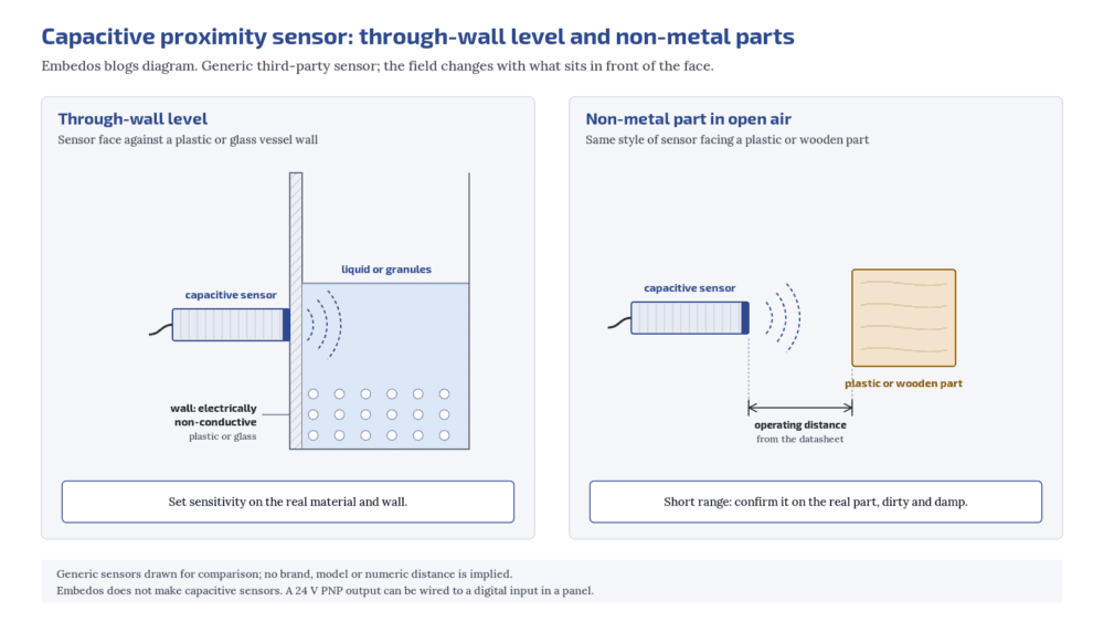
embedos-blogs-capacitive-embedos-level-non-metal: Embedos blogs diagram of a capacitive proximity sensor used for through-wall level and for a non-metal part in open air

Tell us what you need on site

Need this on your plant? Tell us your requirement

How a capacitive proximity sensor works?

A capacitive proximity sensor looks at a change in capacitance in front of its face. An electrode in the sensor forms an electric field with its surroundings.

When a target, conductive or not, enters that field, the capacitance changes and the output switches. Capacitive, inductive, ultrasonic and photoelectric proximity switches are all in the scope of IEC 60947-5-2 .

Two vendor documents are the primary sources for the application notes below.

Pepperl+Fuchs’ knowledge base on capacitive sensor installation describes flush and non-flush mounting, and why a non-flush sensor needs clearance around the sensing element so the side field is not damped by the mounting (Pepperl+Fuchs, capacitive sensors, installation conditions).

Balluff’s basics and installation guide covers through-wall level sensing on a non-conductive vessel, and the need to set sensitivity on the real material (Balluff, Capacitive sensors: basics and installation).

The rated operating distance is usually quoted against a grounded metal target of a stated size.

Other materials, and a different mounting, change that distance. That is why the sensitivity is adjustable, and why you set it on site, not only from the catalogue.

Where capacitive fits: level and non-metal parts

Capacitive is the better choice when:

  • The target is not metal. Plastic parts, wooden pallets, paper, glass, and many films that would be awkward for an inductive sensor.
  • You need a point level in a plastic or glass vessel, a hopper or a pipe. The sensor can be used as a through-wall sensor for a liquid or a granule, provided the wall is electrically non-conductive and thin; Balluff gives a maximum of 4 mm for its standard flush models. Balluff’s guide describes mounting the face tightly against a glass or plastic wall and setting the switch point with the real contents, not with an empty vessel.
  • You want a simple presence bit, not a continuous level in metres. Most capacitive proximity sensors are digital switches. A 4-20 mA capacitive probe exists as a different product family; do not assume a proximity switch will give you an analog level.

Capacitive is usually a poor first choice when the target is metal at short range (use inductive), or when you need a longer distance, a transparent target in open air, or a dusty flight path that a photoelectric would struggle with (consider ultrasonic).
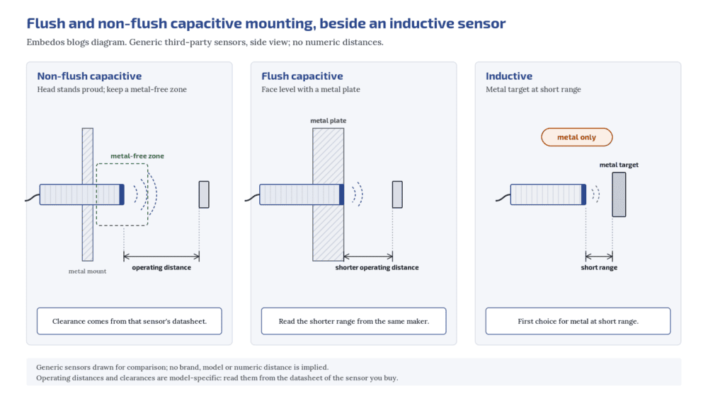
embedos-blogs-capacitive-embedos-flush-nonflush: Embedos blogs diagram of flush and non-flush capacitive mounting beside a short-range inductive sensor on a metal target

Flush or non-flush, and 4-wire

Non-flush (non-embeddable) capacitive sensors are the usual choice when you want the longer operating distance for a given diameter.

Pepperl+Fuchs’ installation note is the source for this: a non-flush sensor needs a clearance around the sensing element, defined in that sensor’s technical data, because some of the field leaves the side of the barrel.

If you bury a non-flush barrel in metal, you will damp it.

Flush (embeddable) models can sit in a metal plate with the face level with the surface.

That protects the barrel and reduces side interference. The same Pepperl+Fuchs note states that, for their flush-mountable capacitive sensors, this is done at the expense of detection range: those sensors achieve only about 60 percent of the operating distance of the non-flush versions.

That figure is Pepperl+Fuchs’, for their flush versus non-flush capacitive sensors. Do not copy it onto another maker’s range, and do not treat it as a universal ratio. If the tender asks for non-flush, confirm the metal-free zone on the datasheet of the model you are buying.

If the only space is a metal wall, use a flush model from that same maker and accept the shorter range that maker states.

4-wire DC in a tender often means a sensor with a supply pair and complementary outputs (normally open and normally closed); confirm the output arrangement on the datasheet, rather than assuming a 2-wire AC or DC switch. Confirm 24 V DC, and confirm a PNP output if the receiving input is a sinking input.

That is the combination this guide can take into EM or EB digital inputs.

Why do capacitive sensors false-trip in dusty or damp plants?

Dust, condensation and nearby metal change the capacitance in front of the face. Set sensitivity on the real material, lock it, and test a dirty or damp face before you accept the job.

Sensitivity, dust and moisture

False trips are the usual reason a capacitive sensor is pulled off a vessel.

Dust on the face, condensation, a wet hopper wall, or a metal guard in the side field can look like the target. Balluff’s installation guide is the source for setting the switch point on the real material, and for leaving margin, because temperature and other environmental factors can cause faulty switching near the limit. The practical steps are:

  • Mount the sensor as it will be used (through-wall or in free air, flush or non-flush).
  • Fill or present the real material, and set the sensitivity or the teach function at that condition, then lock it.
  • Test a dirty or damp face, and a nearby metal guard, on purpose, before you accept the installation.
  • For level through a wall, consider coating or condensation on the probe or on the wall, and whether a flush face sitting tight on the wall is cleaner than a gap that can fill with dust.

If the material has a low dielectric constant, the operating distance shrinks and the setting becomes tighter. If you cannot get a stable setting on the real material, capacitive may be the wrong type; do not turn the pot to maximum and hope.

When is a capacitive sensor better than an inductive one?

When the target is not metal, or when you need to sense a liquid or a bulk material, including through a plastic or glass wall. Inductive remains the first choice for metal at short range.

Specifying capacitive sensors for bulk level or non-metal parts?

Tell us the target material, flush or non-flush, and the input the sensor must drive, and we will help you check the selection.

Flush or non-flush in a metal plate?

Use a flush model if the barrel must sit in metal, and read the shorter range from that maker’s datasheet. Pepperl+Fuchs states about 60 percent of the non-flush operating distance for their flush capacitive sensors; treat that as their figure, not a universal ratio.

Outputs into a gateway or PLC

A capacitive proximity sensor is, in the usual plant case, a 24 V DC digital presence bit. Wire a PNP (sourcing) output to a sinking digital input.

On Maxwell (EM) and Bose (EB), that is a 24 V PNP sensor into a digital input. Those are the input claims we can make. Other output styles need a matching input, which is outside the scope of this guide.

If you need a continuous level rather than a point, use a level transmitter with a 4-20 mA output into an analog input, not a proximity switch. The 4-20 mA current loop is defined in IEC 60381-1 (IEC webstore). Embedos Edge is the platform for that analog path, and the Edge device belongs in a panel, not on the hopper wall.

Also write down the IP rating, washdown, and whether you want a cable or a connector. Those are environmental choices, not detection choices, but they decide whether the sensor survives the first wet shift.

Why do tenders ask for non-flush 4-wire models?

Non-flush usually gives the longer operating distance, provided the metal-free zone is respected. 4-wire DC often means a 24 V sensor with complementary outputs; confirm the output arrangement on the datasheet, and confirm a PNP output if you are driving an EM or EB digital input.

Capacitive proximity sensor selection checklist

Area What to ask or check Red flag
Target Liquid, powder, granule or a non-metal solid recorded Capacitive specified for a short-range metal target
Through-wall Plastic or glass wall, thickness and a tight face recorded Through-wall assumed on a metal vessel
Distance Face-to-target or face-to-wall measured Catalogue range used with no on-site check
Mount Non-flush metal-free zone taken from that datasheet A non-flush barrel buried in metal
Flush Used only if the same maker’s flush range is acceptable A 60 percent figure copied from another maker
Electrical 24 V DC PNP into a matching digital input Output style left as “DC sensor”
Setting Sensitivity or teach set on the real material, then locked Pot left at maximum
False trips Dust, moisture and nearby metal guards tested on site First trip discovered after handover
Level coating Condensation or coating on the face or wall considered Through-wall used on a wall that sweats, with no test
When not capacitive Metal at short range: inductive first; longer range: consider ultrasonic One sensor type specified for every target
Documents Datasheet, mounting sketch, and a note from the false-trip test Brochure only

Where Embedos fits

We do not make capacitive proximity sensors. Choose the sensor from your preferred vendor using the checks above. A 24 V PNP capacitive sensor can be wired to a digital input on Maxwell (EM) or Bose (EB). Embedos Edge is the platform when a related analog signal (for example a 4-20 mA level probe) also needs to be logged. The Edge device goes in a panel.

Download the Free “Capacitive Proximity Sensor Selection Checklist”

Enter your email and the form emails you the copy link to the Google Sheet.


Can a capacitive sensor see through a tank wall?

Yes, if the wall is electrically non-conductive (plastic or glass) and the face sits tightly on it. Set the switch point with the real contents. It will not see through a metal wall.

Can I wire this into an Embedos device?

A 24 V PNP sensor can be wired to a digital input on EM or EB. That is the input path this guide covers. Do not assume other output styles on those inputs.

Next step! Send us a Mail

Send us the stroke, the resolution and speed you need, how the sensor will be mounted (in a cylinder, on a profile or with a wire), the conditions at the sensor head and the input your PLC accepts.

Email: team@embedos.io

Help Us Help You Leverage The Power Of Industrial Automation & Industrial IoT - IIoT.
Load Cell Weighing Module for PLC: Buyer Guide

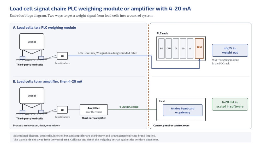
A strain gauge load cell gives a signal of a few millivolts, so it cannot be wired straight into a normal PLC analog input. You have two main ways to get weight into a PLC.

A load cell weighing module for the PLC connects the load cells directly, powers the bridge, reads the millivolt signal and gives the PLC a calibrated weight with tare, zero and filling functions.

A load cell amplifier or weighing transmitter sits near the load cells and converts the signal to 4-20 mA, 0-10 V or a fieldbus value that any analog input or gateway can read.

Choose the weighing module for fast batching, filling and dosing where the PLC acts on weight in real time, or where trade approval is involved (the approval covers the complete weighing instrument, so check that the module is part of an approved model).

Choose an amplifier for tank inventory, monitoring and long cable runs where a standard analog signal is easier to carry and log.

Automation, instrumentation and process engineers specifying tank, hopper or batch weighing in food, chemical, steel and building material plants.

embedos-blogs-load-cell-embedos-signal-chain: Embedos blogs diagram comparing a load cell wired to a PLC weighing module with a load cell wired to an amplifier that sends 4-20 mA to a standard analog input

Tell us what you need on site

Need this on your plant? Tell us your requirement

How a load cell makes its signal

Most industrial load cells are strain gauge types: strain gauges bonded to a metal element, wired as a Wheatstone bridge. FUTEK’s primer covers the main load cell types and how the bridge output changes with load (what is a load cell).

The bridge needs a supply, called excitation, and gives a small output in proportion to it. That is why load cell sensitivity is quoted in mV/V: millivolts of output, at full rated load, per volt of excitation. HBK’s training notes work through it (HBK: pros and cons of amplified force sensors):

  • A 2 mV/V load cell with 5 V excitation gives 10 mV at full load.
  • The same cell with 10 V excitation gives 20 mV at full load.

Now compare that with a standard PLC analog input built for 0-10 V. A 10 mV full-scale signal is one thousandth of the input range. Tiny noise becomes a large weight error, and the input’s own resolution is spread over a range the signal never uses.

That is the whole reason weighing modules and amplifiers exist.

4-wire and 6-wire load cells

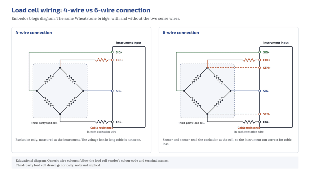
A 4-wire load cell has two excitation wires and two signal wires. The cable resistance drops part of the excitation voltage before it reaches the bridge, so the sensitivity changes with cable length and temperature. HBK’s notes show this effect for 4-wire circuits.

A 6-wire load cell adds two sense wires that measure the excitation at the bridge itself. The instrument uses that reading to correct for the cable, so sensitivity no longer depends on cable resistance. For a 4-wire cell, do not cut or extend the cable without checking the calibration; for long runs, prefer 6-wire cells and a 6-wire instrument.

embedos-blogs-load-cell-embedos-4-wire-6-wire: Embedos blogs diagram of a Wheatstone bridge load cell with 4-wire connection beside the same bridge with two extra sense wires for 6-wire connection

Option A: a weighing module in the PLC

A weighing module is a PLC card built for strain gauge load cells. Siemens’ manual for its SIWAREX WP521/WP522 modules is a good public example of what such a module covers (SIWAREX WP521/WP522 manual):

  • It supplies the load cells (4.85 V on this module) and reads cells rated 1 to 4 mV/V, in 4-wire or 6-wire connection.
  • It requires a junction box when more than one load cell is connected, with the cells wired in parallel.
  • It is calibrated with test weights or adjusted without them using the load cells’ characteristic values.
  • It gives the PLC a weight value directly, with tare, zero and setpoint functions, plus its own digital inputs and outputs and Modbus interfaces.
  • It monitors the load cell wiring for breaks.

When a module wins:

  • Batching, filling and dosing, where the PLC must cut a feeder or valve at a target weight. The module’s own setpoints and digital outputs are built for this job.
  • Multi-ingredient recipes on one vessel, where the weight drives each step.
  • Trade or regulatory use, where an approved weighing chain is needed (see the OIML and Legal Metrology section below).

Trade-offs: you are tied to the PLC platform, the load cell cable must run to the PLC panel (or to an extension box), and commissioning needs someone who knows the module’s calibration procedure.

Option B: a load cell amplifier or weighing transmitter

An amplifier, also called a weighing transmitter or load cell transmitter, sits near the vessel, often next to the junction box. It powers the bridge, amplifies the millivolt signal and outputs 4-20 mA, 0-10 V or a fieldbus value.

When an amplifier wins:

  • Tank and silo inventory, where you need a weight trend, a low-level alarm and a daily figure, not a cut-off in a fraction of a second.
  • Long distances from vessel to panel. A 4-20 mA loop carries the signal much better than a millivolt pair, and the current loop is a standardised signal per IEC 60381-1 (IEC webstore).
  • Mixed systems, where the same weight goes to a PLC, a SCADA and a remote dashboard.
  • Retrofits, where the PLC has spare analog inputs but no slot or budget for a weighing card.

Trade-offs: calibration lives in two places, the span set in the amplifier and the scaling in the PLC, so record both. The analog chain adds its own noise and resolution limits, so check the amplifier datasheet against the smallest weight change you need to see. Tare and zero logic move into the PLC program.

If the amplifier’s analog output feeds channels in the same panel as other loops with different grounds, read our note on 4-20 mA signal isolators and ground loops.

Option C: amplifier plus edge logging

For monitoring only, such as silo stock across sites or a weight trend for maintenance, the 4-20 mA from an amplifier can go to an edge device or gateway that logs it and sends it to a dashboard. The weighing itself is still done by the load cells and amplifier; the gateway only records and transmits the analog value.

Choosing between a weighing module and an amplifier?

Tell us the vessel, the number of load cells and what the weight is used for, and we will help you check the signal chain.

Calibration basics

Whichever option you choose, plan calibration from the start:

  1. Zero (dead load). With the vessel empty and all fixed attachments in place, set zero.
  2. Span with test weights. Add known weights, ideally close to the working range, and set the span. The Siemens manual above describes calibration points defined by calibration weights.
  3. Check linearity. Add and remove weights in steps and record the readings both ways.
  4. Theoretical adjustment using each load cell’s characteristic value (its certified mV/V) is possible on some instruments when test weights cannot be placed, for example on a large silo. Treat it as a starting point and verify with a known material quantity where you can.

Record the calibration date, the weights used and the readings. For the amplifier route, also record the amplifier span and the PLC scaling.

Noise and installation

Most weighing problems are mechanical or wiring, not electronic:

  • Cable. Use shielded, twisted-pair load cell cable and earth the shield as the instrument manual specifies; the Siemens manual requires shielded twisted pairs for sense, signal and supply wires and grounds the shield close to the module. Keep load cell cables away from motor and VFD power cables.
  • Junction box. Where several load cells are summed, use a proper junction box and keep it dry.
  • Mechanical forces. Rigid pipes, cable trays or walkways attached to a weighed vessel carry part of the load and spoil the reading. Mettler Toledo’s vessel piping guide shows how to lay out pipes and flexible connections so they do not push or pull on the vessel (vessel piping design).
  • Vibration and wind. Agitators, nearby machines and wind on outdoor silos add noise. Instrument filters help but slow the reading, which matters for fast filling.

OIML R76, R60 and Legal Metrology in India

If weight is used only to run the process, you are doing process weighing. If you sell, buy or charge by that weight, it is trade weighing and legal metrology rules apply.

  • OIML R 76 covers non-automatic weighing instruments (OIML R 76:2006). It classifies instruments by the verification scale interval (e), which represents absolute accuracy, and the number of verification scale intervals (n = Max / e), which represents relative accuracy, into four accuracy classes: special (I), high (II), medium (III) and ordinary (IIII) (R 76-1 text).
  • The verification scale interval is not the same as the display division (d). NIST explains the difference clearly (NIST: d versus e).
  • OIML R 60 is the metrological regulation for load cells (OIML R 60:2017). Load cell datasheets often quote an OIML R 60 class; read it together with the instrument requirements, not on its own.
  • India. Weighing instruments used for trade need model approval under the Legal Metrology Act, 2009 and the Legal Metrology (Approval of Models) Rules, 2011 (the Act and Rules are published by the Department of Consumer Affairs: Legal Metrology Act and rules). If your weight will appear on an invoice, involve your legal metrology contact before you choose hardware.

Load cell weighing module for PLC: buyer checklist

Item PLC weighing module Amplifier / weighing transmitter
Purpose Batching, filling, dosing, trade Inventory, monitoring, long runs
Load cell input mV/V range the module accepts; 4 or 6-wire mV/V range the amplifier accepts; 4 or 6-wire
Number of cells Junction box for more than one Junction box for more than one
Output to PLC Weight value over the backplane or Modbus 4-20 mA, 0-10 V or fieldbus
Cable to panel Load cell cable or extension box 4-20 mA pair
Calibration In the module: weights or characteristic values In the amplifier, plus scaling in the PLC
Tare and zero In the module In the PLC program
Setpoints Module setpoints for cut-off PLC logic on the analog value
Trade use Check the approved weighing chain Usually process only
Installation Shielded twisted pairs; flexible vessel connections Same

Where Embedos fits

We do not make a weighing module or a load cell amplifier.

Where weight is needed for monitoring, a third-party load cell amplifier or weighing transmitter can send its 4-20 mA or 0-10 V output into an analog input on an Embedos Edge device, an Embedos Maxwell (EM) card or an Embedos Bose (EB) HMI, which then logs and displays the value.

Download the Free “Load Cell Signal and Calibration Worksheet”

Enter your email and the form emails you the copy link to the Google Sheet.


Common questions

Can I connect a load cell directly to a PLC analog input?

No, not to a standard 4-20 mA or 0-10 V input. The load cell gives millivolts. Use a weighing module or an amplifier between them.

What does 2 mV/V mean?

At full rated load, the load cell outputs 2 mV for every volt of excitation. With 10 V excitation that is 20 mV at full load.

Weighing module or 4-20 mA amplifier for a silo?

For stock monitoring, an amplifier with 4-20 mA is usually simpler. For filling to a target weight, a weighing module reacts faster and keeps the logic in one place.

Why is my tank weight drifting?

Check mechanical connections first: rigid pipes, cable trays or walkways touching the vessel. Then check cable shielding, moisture in the junction box and temperature effects on 4-wire cables.

Do I need a legal-for-trade weighing system?

Only if the weight is used for trade, such as selling or charging by weight. In India, weighing instruments used for trade must be of a model approved under the Legal Metrology Act, 2009 and the Approval of Models Rules, 2011.

How many load cells does a tank need?

That depends on how the vessel is supported. Follow the load cell maker’s mounting guidance and use a junction box to sum the cells.

Next step! Send us a Mail

Send us the stroke, the resolution and speed you need, how the sensor will be mounted (in a cylinder, on a profile or with a wire), the conditions at the sensor head and the input your PLC accepts.

Email: team@embedos.io

Help Us Help You Leverage The Power Of Industrial Automation & Industrial IoT - IIoT.
Inductive vs Photoelectric Sensor: Plant Selection Guide by Embedos Mumbai!

Does stainless steel reduce sensing distance?

Yes, for most inductive sensors. Check the vendor’s guidance for your target material, or choose a sensor rated for all metals.

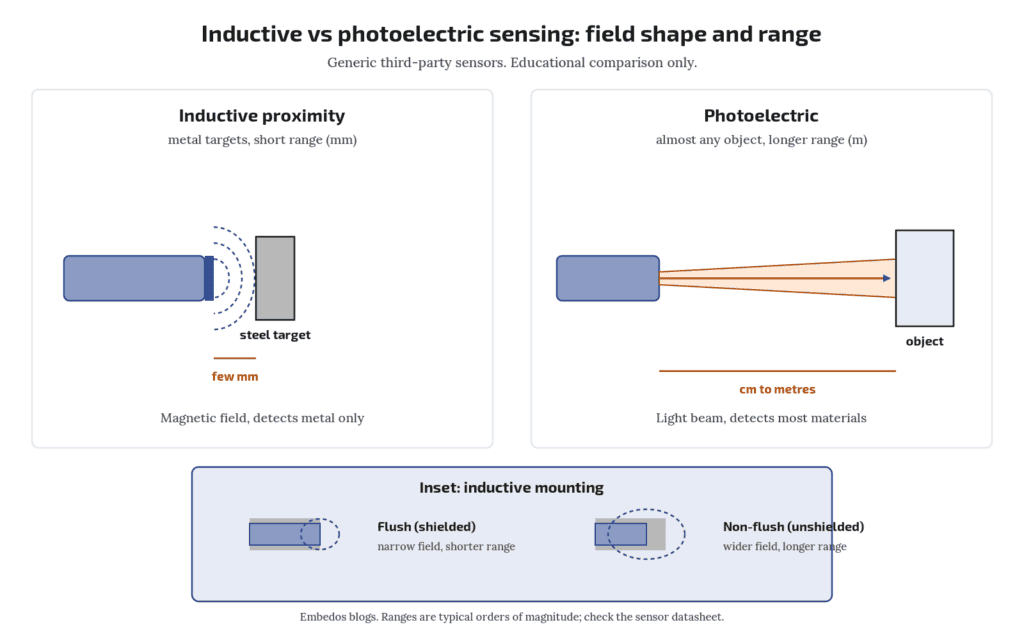
In the inductive vs photoelectric sensor choice, use an inductive sensor when the target is metal and can come within a few millimetres to a few tens of millimetres of the sensor face.

It ignores dust, light and most dirt.

Use a photoelectric sensor when the target is non-metallic, far away (tens of centimetres to metres), or must be detected by edge or colour.

In dusty steel and power plants, inductive is the default wherever geometry allows, because dust that blinds an optical lens does not affect an inductive field.

The requirement should specify 3-wire DC, PNP or NPN to match the input card, flush or non-flush mounting, sensing distance, and IP rating per IEC 60529.

Who this is for: instrumentation and electrical engineers writing sensor specs for conveyors, rotating shafts, gates and position feedback in heavy-process plants.

Flush or non-flush?

Non-flush for longer range when a metal-free zone is possible. Flush when the sensor must sit level with metal.

Tell us what you need on site

Need this on your plant? Tell us your requirement

Embedos blogs embedos-blogs diagram: inductive sensor field detecting a steel target at short range versus photoelectric beam detecting an object at longer range

How each one works, in one line

  • Inductive proximity: An oscillator makes a high-frequency field at the face; a metal target in the field draws energy (eddy currents), and the output switches. Construction and test requirements for proximity switches are covered in IEC 60947-5-2.
  • Photoelectric: an emitter sends light (usually red, infrared or laser); the receiver switches when the beam is broken or reflected. Modes are through-beam, retro-reflective and diffuse. IEC 60947-5-2 also covers photoelectric proximity switches.
PNP or NPN?

Match the input card. Sinking inputs take PNP; sourcing inputs take NPN.

Inductive: what to check

Target material. Rated sensing distance (Sn) is stated for a standard mild steel target. Other metals reduce it; stainless steel, brass, aluminium and copper all give shorter range. Use the correction factors (or equivalent guidance) from the inductive sensor datasheet for your target metal; do not design to the mild-steel Sn alone.

Assured operating distance. Do not design to Sn. Use the assured switching distance (Sa) from the datasheet (typically about 80% of Sn, after tolerances), and leave margin for shaft run-out and wear.

Flush vs non-flush.

  • *Flush (shielded)*: Can be mounted with the face level with surrounding metal. Shorter range.
  • *Non-flush (unshielded)*: The field spreads sideways, so it needs a metal-free zone around the face, but gives longer range. Requirement specs for heavy plants often ask for non-flush to get more air gap from a moving target, which reduces the chance of a strike.

Size and thread. M12, M18 and M30 are common; larger bodies give longer range. Specify a robust housing (stainless or nickel-plated brass) and lock nuts.

Temperature. Near furnaces and hot shells, check the maximum ambient on the datasheet. Use a heat shield or high-temperature variant where needed.

Can an inductive sensor see through dust and scale?

Yes for non-metallic dust. Metallic dust or mill scale building up on the face can trigger it falsely, so keep the face clean or angle it so scale falls off.

Photoelectric: what to check

Mode.

  • Through-beam: Separate emitter and receiver; longest range and most tolerant of dirt, because there is the most light margin.
  • Retro-reflective: One body plus a reflector; easier to wire, shorter range. Use a polarised version for shiny targets.
  • Diffuse: Reflects off the target itself; shortest range, most affected by target colour and dust.

Excess gain. Sensor manufacturers publish excess gain curves: how many times more light reaches the receiver than needed to switch. Dusty areas need high excess gain. Read the curve on your sensor’s datasheet and choose more margin as contamination rises.

Lens care. Fit air purge or a protective hood in coal handling, sinter and cement areas, and add lens cleaning to the maintenance schedule.

When must I use photoelectric?

When the target is non-metallic (belts, coal, paper, wood, glass), when the gap is too large for an inductive, or when you need to detect an edge or presence at distance.

Download the Free “Inductive vs Photoelectric Selection Checklist”

Enter your email and the form emails you the copy link to the Google Sheet.


Inductive or photoelectric for a dusty conveyor?

Inductive if you can sense a metal part (pulley, flag, shaft) at short range. Use photoelectric with high excess gain and lens protection only if you must sense the belt or material.

Electrical: 3-wire DC, PNP or NPN

Most requirement specs ask for 3-wire DC: brown +V, blue 0 V, black output (common colour code, check the datasheet). Output type must match the input card:

  • PNP (sourcing): switches +V to the load. Pairs with sinking PLC inputs. Common in India and Europe.
  • NPN (sinking): switches 0 V to the load. Pairs with sourcing inputs.

Also specify:

  • NO or NC output, or both (4-wire complementary).
  • Supply range, often 10 to 30 V DC.
  • Short-circuit and reverse-polarity protection.
  • Switching frequency, if you are counting teeth or slots on a shaft. A sensor that cannot switch fast enough will drop pulses at full speed.
  • Connector or cable: M12 connectors simplify replacement; a fixed PVC or PUR cable may suit hot or oily areas better. Connector interfaces for M12 are standardised in IEC 61076-2-101:2024.

2-wire DC sensors exist and save a core, but they have higher leakage current and residual voltage that some input cards misread. State 3-wire if in doubt.

IP rating and dust

Degrees of protection are defined in IEC 60529. The first digit is solids, the second is water:

  • IP65: dust-tight (6) and protected against water jets (5). Common minimum for heavy-plant Requirements.
  • IP67: dust-tight and protected against temporary immersion.
  • IP68 / IP69K: higher immersion or high-pressure washdown (IP69K is from ISO 20653, for road vehicles, often quoted by sensor makers).

IP covers the enclosure. Cable glands and connectors must match, or the assembly is only as good as the weakest part.

Requirement checklist

Item Inductive Photoelectric
Target Metal; state material Any; state material, colour, size
Range Sn and assured distance, flush or non-flush Mode and range; excess gain at that range
Body M12 / M18 / M30, metal housing Housing material, hood or air purge
Electrical 3-wire DC, PNP/NPN, NO/NC, 10-30 V DC Same, plus light-on / dark-on
Frequency Switching frequency for counting Response time
Protection IP65 min per IEC 60529; temperature IP65 min; lens protection
Connection M12 or cable length and jacket Same
Standard IEC 60947-5-2 IEC 60947-5-2

Using the signal

A proximity sensor’s pulse train is the usual input for speed, zero-speed and length counting. Applications related to speed and distance.

Embedos Edge Products have very fast hardware counters to take inputs.

One Example:

Our Em Bose (EB) 3.2″ HMI measures speed and length counter takes a pulse or frequency signal from a third-party proximity sensor and shows speed, length or RPM (EB length counter, speed monitor and RPM meter).

For belt and direct drives, see our motor-side vs fan-side RPM notes. The sensor itself is chosen with a pre qualified criteria. 

Is IP65 enough?

For dust and jets, usually. For immersion or washdown, specify IP67 or higher.

Next step! Send us a Mail

Send us the stroke, the resolution and speed you need, how the sensor will be mounted (in a cylinder, on a profile or with a wire), the conditions at the sensor head and the input your PLC accepts.

Email: team@embedos.io

Help Us Help You Leverage The Power Of Industrial Automation & Industrial IoT - IIoT.
When a timezone setting becomes a root shell: Four OT edge lessons in Cyber Security to learn in Industrial Automation

Most of us treat the timezone field on a device web page as the least dangerous setting on the box.

You pick “Asia/Kolkata”, click save, move on. One of the late-October CISA advisories shows how that field can end with an attacker holding full control of a transformer monitor.

This post walks through that case and three sibling advisories from the same fortnight. The goal is simple:

1) Things a firmware engineer can change in the next build,

2) Questions a plant buyer can ask a vendor before the next purchase order.

Tell us what you need on site

Need this on your plant? Tell us your requirement

The lead case: a timezone handler that builds a shell command

On 29 October 2026, CISA published ICSA-26-302-03 for Hitachi Energy CoreTec, the transformer monitoring product line. Two CVEs are in it.

CVE-2026-13162, configuration to command execution. Per the advisory, the bug lets authenticated users with certain roles execute arbitrary system commands with full control over the device.

The location is specific: the configuration daemon’s time synchronization handler, which sets the system timezone. When it processes a timezone update, the daemon constructs a shell command by concatenating user-supplied input without any sanitization or validation. CISA classes it as CWE-78, CVSS v3.1 base score 7.5.

Affected versions are CoreTec4 and CoreTec5 3.4.0 and prior, with CoreTec5 version 5.0.0 as the vendor fix.

CVE-2026-43284, a kernel feature nobody needed at the edge. The second CVE is in the Linux kernel IPsec ESP subsystem (esp4) used in CoreTec5, letting a local unprivileged user escalate to root. The detail worth reading twice: in CoreTec5, the vulnerable ESP component is compiled into the kernel as a built-in and is present at boot. It scores CVSS v3.1 8.8.

Put the two together and you get a familiar chain shape: a configuration path that reaches a shell, and a kernel that ships more attack surface than the product uses.

What went wrong, in engineering terms

Nothing here is exotic. It is the pattern most of us have written at least once:

# illustrative only, not vendor code
system("timedatectl set-timezone " + tz_from_request);

Three decisions stack up:

  1. A config value reaches a shell interpreter. Once a string goes through

    sh -c,

    characters like ;, $( ), backticks and newlines are code, not data.

  2. Role checks in the web UI do not help if the role that can change time settings is wider than the role that should run commands.
  3. No allow-list on a field that has a tiny valid set. Timezones are a finite list. NTP servers are hostnames or IP addresses. Neither needs free text.
  4. The daemon runs with privileges far above the job. Setting a timezone needs write access to one link or one file. It does not need root over the whole device.

The kernel side is a separate lesson. A built-in feature cannot be unloaded or blacklisted in the field. If the product does not terminate IPsec on that box, the cheapest fix is the one done at build time: do not compile it in.

Firmware-side fixes you can apply this sprint:

  • Never pass config values to a shell. Call the binary directly with an argument array (execve-style), or better, write the file yourself.
  • Validate against an allow-list: the tz database list for timezones, a strict hostname or IP parser for NTP.
  • Run config daemons as a dedicated user with only the capabilities they need. Split “write config” from “apply config”.
  • Audit kernel =y options against what the product actually does. Drop unused network protocol families, filesystems and debug features.

Three sibling patterns from the same fortnight

B. “Localhost-only” is not a security boundary

Also on 29 October, CISA published ICSA-26-302-02 for Hitachi Energy TRO600 series. CVE-2026-10756 lets an authenticated attacker bypass network access restrictions and reach services intended to be reachable only from localhost, by using port forwarding. A second CVE, CVE-2026-106087, lets an unauthenticated attacker read or download arbitrary files, including configuration files and password data. The advisory lists 9.2.1.6 and prior as affected, with 9.2.2.1 as the update.

The lesson for designers: binding an admin service to 127.0.0.1 reduces exposure, it does not authenticate anyone. Any SSH tunnel, reverse proxy or helper process on the box can turn “local” into “remote”. Internal services still need their own authentication, and port forwarding should be disabled unless the product needs it.

Reviewing edge firmware for your plant?

Tell us what you are checking and we will get back to you.

C. A general-purpose Linux runtime on a controller is a patch obligation

On 22 October, ICSA-26-295-11 covered the additional GNU/Linux subsystem of firmware V3.1.7 on the SIMATIC S7-1500 CPU 1518(F)-4 PN/DP MFP, including the SIPLUS variant. The CISA page lists 428 vulnerabilities for the product. Siemens states that no fix is currently available and fixes are being prepared. Interim mitigations are to limit interactive shell access of the GNU/Linux subsystem to trusted personnel and only build and run applications from trusted sources. The vendor advisory is Siemens ProductCERT SSA-457936.

This is not a knock on any one vendor. Any product that ships a general-purpose distribution inherits that distribution’s CVE stream. The useful questions are about discipline: Is there an SBOM? How fast do upstream fixes reach a signed update? Can the update be applied in a plant shutdown window without a site visit?

D. A poller that does not check who it is talking to

ICSA-26-295-18, also 22 October, lists Siemens RUGGEDCOM APE1808 with Nozomi Guardian/CMC as affected. It is a republication of Siemens ProductCERT SSA-911336. The CVE that matters for poller design is CVE-2026-33389: the Smart Polling feature established encrypted connections to target devices without validating the remote host’s identity, with no option to enable it. A man-in-the-middle can then impersonate the device, capture the credentials, and replay them against that device or other devices sharing the same credentials. Siemens advises contacting customer support for patch information.

Encryption without identity checks only tells you nobody else can read the session. It does not tell you who is on the other end. And shared credentials across a fleet turn one captured password into many.

A checklist for edge designers and buyers of Automation Control Products (Not Gated, because we understand its seriousness)

Use this as a design review list, or attach it to an RFQ for gateways, edge controllers and monitoring units.

Configuration handling

  • Does any configuration field (timezone, NTP, hostname, DNS, SNMP community, alarm script) ever reach a shell? Ask the vendor to say so in writing.
  • Are inputs validated against allow-lists, not just length limits?
  • Which role can change time and network settings, and is that role narrower than “admin”?

Least privilege on the box

  • Which daemons run as root? Which ones need to?
  • Is the kernel configuration trimmed for the product, or is it a stock build with everything built in?
  • Are debug shells and interactive consoles disabled or restricted in production images?

Internal services

  • List every service bound to localhost. Does each one authenticate on its own?
  • Is SSH port forwarding or tunnelling disabled unless explicitly needed?
  • Can an unauthenticated request read any file? Ask for the vendor’s last penetration test scope, not just the result.

SBOM and updates

  • Is a machine-readable SBOM available for every firmware release?
  • What is the vendor’s stated time from upstream CVE to signed update?
  • Are updates signed, verified on the device, and rollback-safe? Can they be staged for a shutdown window?
  • If no fix exists yet, what interim mitigations does the vendor publish?

Polling and peer identity

  • Does every poller (Modbus TCP gateways, SNMP, SSH, HTTPS, OPC UA clients) verify the identity of the device it connects to?
  • Can certificate or host key validation be turned on, and is it on by default?
  • Are field device credentials unique per device or per zone, and rotatable?

None of this needs a new product. Most of it is a design review and a few pointed questions before purchase.


Next step

At Embedos we build and commission the Embedos Edge platform (products, solutions, dashboards, insights and services for industrial data).

If you are reviewing edge or gateway firmware for a plant and want a second pair of engineering eyes,

try our free utilities on tools.embedos.io.

or write to us at Email: team@embedos.io

Help Us Help You Leverage The Power Of Industrial Automation & Industrial IoT – IIoT.

Short-Range Radar Level Transmitter: Picking for 0.1-1.6 m

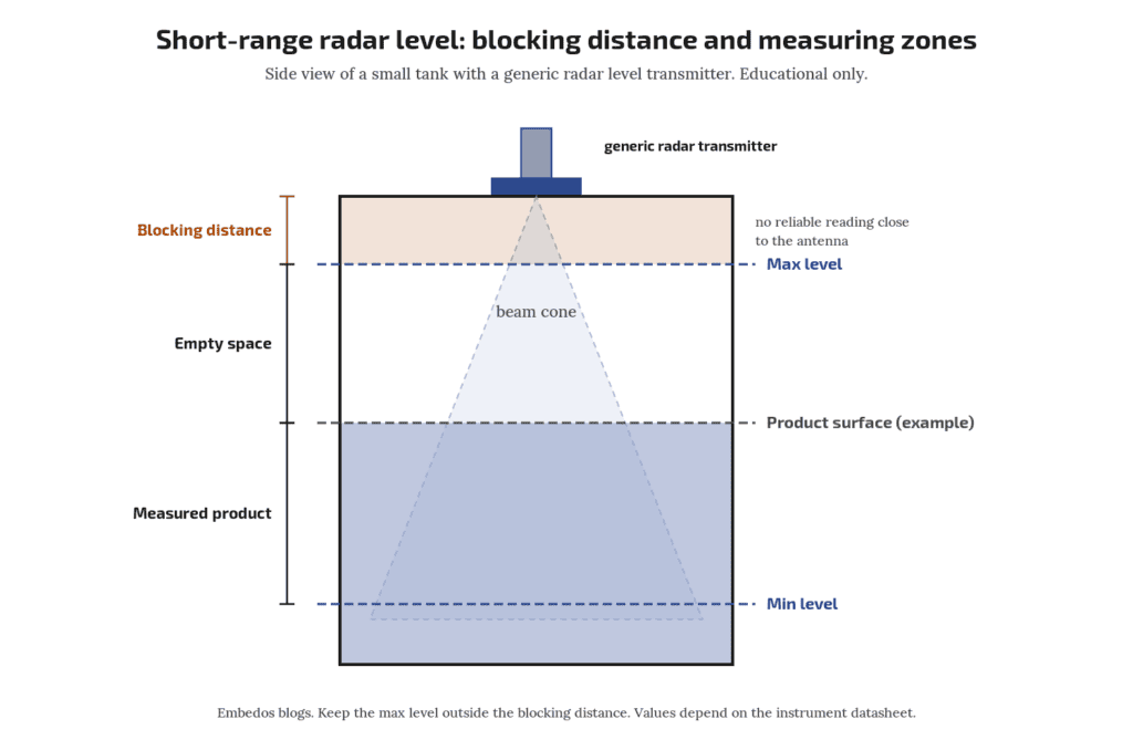
For a short range radar level transmitter on a vessel where the liquid sits 100 mm to 1600 mm below the flange, the spec that decides everything is the blocking distance (also called dead band or near-range limit).

If the maximum level comes closer to the antenna than that distance, the reading is not valid. After that, check beam angle (higher frequencies such as 80 GHz give a narrower beam from a smaller antenna), mounting position, and how you scale 4-20 mA. On short ranges, a few tens of millimetres matter.

Who this is for: Instrument and process engineers fitting level measurement on day tanks, dosing tanks, small buffer vessels and sumps under 2 m tall. Operators working with cranes, material handling equipment, logistics, supply chain equipment, process autoamtion requirements, to detect objetcs automatically, over a distance. 

Tell us what you need on site

Need this on your plant? Tell us your requirement

Embedos blogs embedos-blogs diagram: radar level transmitter on a small tank showing blocking distance, maximum level, minimum level and beam cone

Blocking distance dominates short ranges

A short range radar transmitter measures time of flight of a microwave signal reflected from the surface. Close to the antenna, the transmitted signal and nozzle reflections mask the echo, so vendors state how close to the antenna the level may come.

For example, Endress+Hauser Technical Information TI01683F/00/EN/01.22 for the 80 GHz Micropilot FMR60B states that the range measures to the antenna tip and recommends ending the measuring range 10 mm before the tip (Endress+Hauser Micropilot FMR60B). Always read the near-range limit from your model’s own Technical Info.

Rule of thumb:

Maximum level must stay below the blocking distance plus a safety margin, measured from the antenna reference point stated in the manual (not always the flange face).

Worked example: (hypothetical figures, not from TI01683F or any one model): tank top flange to bottom 1700 mm. Assumed blocking distance 100 mm from the reference point.

Maximum level allowed = 1700 − 100 − 50 margin = 1550 mm of liquid.

If the overflow sits higher, raise the nozzle or choose a model with a shorter near zone.

What if the tank sometimes overfills into the blocking zone?

The reading can freeze or jump. Add an independent high-level switch for overfill protection; do not depend on the radar in its own blind zone.

Frequency and beam angle

Beam angle is narrower for higher frequency and larger antenna. 80 GHz instruments give a narrow beam from a small antenna, which helps on small tanks where walls, agitators and ladders are close.

For example, VEGA brochure 52552 for the 80 GHz VEGAPULS 64 mentions a beam angle of only 3° with an 80 mm antenna (DN 80 / 3″ flange); smaller antennas give wider beams, so check the figure for the antenna you order (VEGA brochure 52552, VEGAPULS 64).

Level probing radar use is regulated in Europe under ETSI EN 302 729 (ETSI). For India, confirm vendor WPC/DoT type approval for the instrument. Note that DoT notification G.S.R. 468(E) of 11 June 2026 delicenses 77 to 81 GHz for vehicle radar only; it does not cover tank level radar.

Mounting on small vessels

Keep the beam clear of walls, inlet streams and agitator blades.

Vendors usually advise mounting away from the centre (to avoid multiple reflections from a domed roof) and away from the inlet.


  • Short nozzles: long or narrow nozzles add false echoes near the antenna, which effectively extends the dead zone. Follow the maker’s nozzle length and diameter limits.
  • Foam and condensation: both weaken or scatter echoes. Ask the vendor about the product’s behaviour with your medium.
  • Run a false echo map (mapping) with the tank empty or at low level during commissioning.
Should 4-20 mA represent level or distance?

Usually level from the tank bottom, scaled to the usable span.

Quickly get in touch

Have to make a similar decision? Our Engineers will reply to you immediately!

Is 80 GHz better for small tanks?

Often, because a narrower beam from a small antenna avoids walls and internals. Check your medium and nozzle with the vendor.

4-20 mA scaling for short ranges

Decide whether 4-20 mA represents level (from the bottom) or distance (from the antenna). Most plants want level.

  • Set empty (4 mA) at the bottom reference and full (20 mA) at maximum usable level, not at the flange.
  • Level = (mA − 4) ÷ 16 × span. With a 0-1500 mm span, 12 mA = 750 mm.
  • On a 1.5 m span, 1 mm = about 0.011 mA. Check that your analog input resolution and the transmitter’s stated accuracy are adequate. The 4-20 mA signal range is defined in IEC 60381-1 .
  • For volume on a horizontal or dished tank, apply a strapping table in the PLC or display, not a straight line.

Check your own numbers with the free Embedos | –  4-20 mA loop scaling calculator.

Quick selection checklist

Check Question
Blocking distance Is max level below it, with margin?
Reference point Where does the manual measure from?
Frequency and beam Clear of walls and internals?
Nozzle Within maker’s length and diameter limits?
Medium Foam, vapour, condensation, low dielectric?
Output 4-20 mA scaled to level, fault current set
Overfill Separate high-level switch fitted?
Do I still need a high-level switch?

Yes, for independent overfill protection.

Showing level and alarms

Once the short range radar transmitter gives a clean 4-20 mA signal, it can be displayed, alarmed and logged.

Our Embedos Em Bose (EB) Series _ tank-level solution displays level and alarms from a third-party sensor

The live page primary path is a sensor at the tank bottom; a distance or level sensor can also feed the display ( relative density calculation then will be different depending on the type of sensor mounting).

What is blocking distance on a radar level sensor?

The zone near the antenna where the instrument cannot measure. Maximum level must stay outside it.

Next step! Send us a Mail

Send your tank drawing, nozzle size and level range, and we will help you check the fit.
Email: team@embedos.io

Help Us Help You Leverage The Power Of Industrial Automation & Industrial IoT – IIoT.

Absolute Linear Position Sensor: 0-1200 mm | magnetostrictive vs laser vs lvdt vs draw wire |Guide

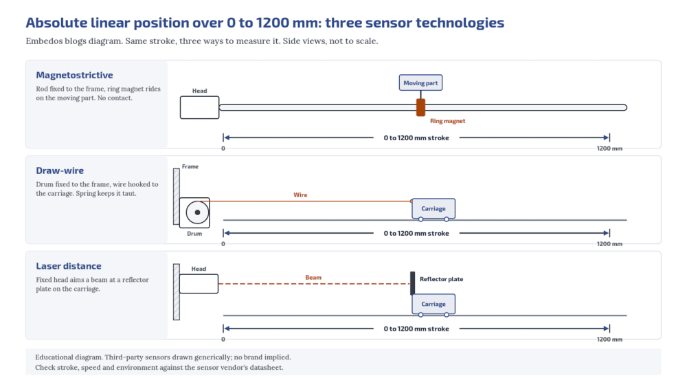
An absolute linear position sensor over 0 to 1200 mm, the usual shortlist is:

A magnetostrictive sensor (non-contact, mounted in a hydraulic cylinder or as an external profile),

or

A draw-wire sensor (a spring-loaded wire on a drum turning an absolute encoder or potentiometer)

or

A laser distance sensor (non-contact, needs a clear line of sight).

Potentiometric rod sensors suit shorter strokes, and LVDTs are mostly used for short strokes.

“Absolute” means the sensor reports the true position at power-up, with no homing run.

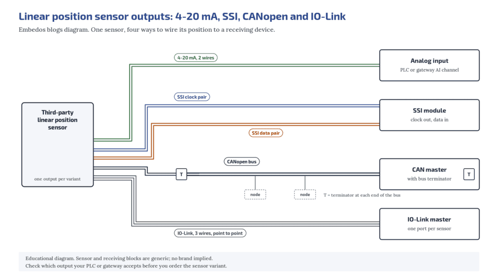
For the output, choose by what the PLC can take: 4-20 mA is the simplest and works with any analog input; SSI gives a digital absolute value over a differential line to a PLC with an SSI interface; CANopen and IO-Link need a matching master.

When selecting, search for ddetails around stroke, resolution, speed, mounting and output, not around one technology name.

Who this is for: instrumentation, hydraulics and automation engineers in steel plants and heavy industry writing a tender or replacing a position sensor on a cylinder, gate, roll gap, carriage or damper.

embedos-blogs-linear-position-embedos-technologies: Embedos blogs diagram comparing magnetostrictive, draw-wire and laser distance sensors measuring a 0 to 1200 mm stroke

Tell us what you need on site

Need this on your plant? Tell us your requirement

What “absolute” means, and why manufacturing companies ask for it?

An incremental sensor counts pulses from a reference point. After a power cut, it has to be driven to a home position before the reading means anything.

An absolute sensor gives the real position as soon as it powers up.

On a hydraulic cylinder, a gate or a roll gap, homing after every power dip costs time and can be unsafe. That is why tenders specify absolute sensing.

The magnetostrictive principle, for example, gives an output that corresponds to absolute position and does not need re-homing after a power loss.

Potentiometric sensors also give an absolute output after power loss.

Draw-wire sensors are absolute only when the drum drives an absolute encoder or a potentiometer, not an incremental encoder.

Magnetostrictive sensors

A magnet rides on the moving part, outside a rod or profile that holds a ferromagnetic waveguide.

The electronics send a short current pulse down the waveguide.

Where the pulse’s field meets the magnet’s field, a torsional strain pulse starts and travels back to the sensor head at a known speed.

The travel time gives the position.

Why they suit 0 to 1200 mm. There is no contact between the magnet and the sensing element, so nothing wears.

Rod styles fit inside a gun-drilled hydraulic cylinder piston rod, which protects the sensor from the plant environment, and profile styles mount outside a machine. Catalogue stroke ranges for this type run well beyond 1200 mm.

Some datasheets lists profile and rod strokes in the metres.

What to check. Stroke and the dead zones at each end, the magnet type and how it is mounted, cylinder bore and pressure rating for rod styles, the output and update time, and the temperature at the sensor head.

Draw-wire sensors

How they work. A flexible steel wire is wound on a constant-diameter drum held under tension by a spring. The sensor body is fixed; the wire end hooks to the moving part.

As the part moves, the drum turns a potentiometer or an encoder, giving an output proportional to the wire extension.

Why they suit 0 to 1200 mm. They are compact for the stroke and easy to retrofit, because the body mounts at one point and only the wire end attaches to the moving part.

What to check. The reel mechanism limits how fast the target can move. Temperature changes affect the wire length and a potentiometer’s resistance. Keep the wire path clear of scale, sharp edges and anything that could snag it, and protect the drum from dust and water.

Confirm the variant is absolute.

Potentiometric rod sensors

How they work. A wiper on the rod slides along a conductive plastic resistance track. With a supply across the track, the wiper voltage is proportional to position, and the output stays absolute after power loss. 

The wiper should feed a high-impedance input; the LWG datasheet linked below recommends a wiper current of no more than 1 µA.

Fit for 0 to 1200 mm. Check the vendor’s stroke range first. One pivot-head series, for example, is listed up to 750 mm (Novotechnik LWG datasheet), which is short of a 1200 mm stroke.

The wiper is a contacting part, so consider cycle life on a fast, continuously moving axis.

Can an LVDT measure 1200 mm?

Rarely. Most catalogue LVDTs cover a few millimetres to a few hundred, and the longest reach about ±500 mm with a body well over a metre long. For 1200 mm, look at magnetostrictive, draw-wire or laser sensors first.

LVDTs

A Linear Variable Differential Transformer (LVDT) is a displacement sensor. It has a primary coil and two secondary coils around a movable soft-magnetic core.

An oscillator drives the primary; as the core moves, the voltage rises in one secondary and falls in the other, and the difference is proportional to displacement.

They are non-contact and well proven.

They need AC excitation and a demodulating conditioner, which DC-operated models build in. Common catalogue ranges are short: the Micro-Epsilon manual covers ±1 to ±25 mm.

Long-stroke LVDTs exist, with one maker listing up to ±500 mm (Messotron DGO), but the body is longer than the full stroke (1420 mm installed for ±500 mm). For 1200 mm, look at the other types first.

Laser distance sensors

A laser distance sensor measures to a target plate or surface on the moving part without touching it.

Long-range models are sold for cranes and for positioning hot steel slabs in steel mills, with analog, SSI and fieldbus interfaces depending on the variant (SICK Dx1000 overview).

For a 1200 mm stroke they make sense when nothing can be attached along the stroke, or when the target is hot.

They need a clear line of sight and a suitable target surface, so plan for dust, steam and anything that could cross the beam.

What happens to a 4-20 mA position signal if the cable breaks?

The current drops towards 0 mA. If the sensor and input follow NAMUR NE 43 levels, the system can flag the fault instead of reading position zero.

Writing a tender for a position sensor?

Send us the stroke, the mounting and the PLC input you have, and we will help you check the spec before it goes out.

Is SSI better than 4-20 mA?

SSI sends a digital absolute value, so cable noise does not change the reading, but the PLC needs an SSI module and both ends must agree on word length, code and clock rate. 4-20 mA works with any analog input.

Outputs: 4-20 mA, SSI, CANopen and IO-Link

4-20 mA (or 0-10 V).

The simplest choice. Any PLC or gateway analog input can read it, and the current loop is standardised in IEC 60381-1. Over 0 to 1200 mm, the 16 mA span works out to about 0.0133 mA per mm.

How finely your system can resolve that depends on the analog input card, the cable and the noise in the panel, so check the input card’s datasheet against the smallest position change you need.

Use NAMUR NE 43 failure levels if the sensor supports them, so a broken loop is not read as position zero. 

For noisy panels, see our note on 4-20 mA signal isolators and ground loops.

SSI (Synchronous Serial Interface).

A digital, absolute interface. The controller drives a clock line and the sensor answers on a data line, sending the position in step with the clock.

The physical layer is differential RS-422, which gives good noise immunity over long cables; the usable clock rate falls as the cable gets longer.

One magnetostrictive SSI series, for example, sends a 24, 25 or 26-bit value in binary or Gray code (Temposonics T-Series SSI manual).

The PLC needs an SSI input module, and the tender must state word length, code (binary or Gray) and clock rate so both ends match.

CANopen.

A CAN-based protocol maintained by CAN in Automation (CANopen).

The CiA 406 encoder profile specifies the application interface for absolute rotary and linear encoders, so a CiA 406 sensor presents position in a standard way (CiA 406 encoder profile).

You need a CANopen master and correct bus termination. For CAN basics, read our beginner’s guide to CAN bus.

IO-Link.

A point-to-point digital link between one IO-Link master port and one device over a standard 3-wire sensor connection, standardised as IEC 61131-9 (IEC 61131-9:2022).

It carries the position plus parameters and diagnostics. It is not a fieldbus; the master connects upward to the PLC network.

Which to pick. If the PLC already has an SSI card or a CANopen or IO-Link master, use it. If the value is only for monitoring and logging, or the panel has spare analog inputs, 4-20 mA is the low-risk choice. Ask for the output you can actually connect on day one.

embedos-blogs-linear-position-embedos-outputs: Embedos blogs diagram of four output paths from a linear position sensor: 4-20 mA to an analog input, SSI to an SSI module, CANopen to a CAN master and IO-Link to an IO-Link master

Steel plant mounting notes

  • Inside the cylinder where possible. A rod-style magnetostrictive sensor inside a hydraulic cylinder is shielded from scale, water and impact; only the head and connector sit outside.
  • Heat at the head. Check the operating temperature for the sensor electronics, not just the rod, and add a heat shield or move the head away from radiant heat.
  • Cables. Use shielded cable, route it away from motor and VFD power cables, and protect it from hot scale and mechanical damage.
  • Electronics in the panel. Signal conditioners, SSI modules, masters and loggers belong in a panel or control room, not in the mill bay.
Magnetostrictive or draw-wire for 1200 mm?

Magnetostrictive for non-contact sensing, high cycle counts and mounting inside a hydraulic cylinder. Draw-wire for a compact, low-effort retrofit where the wire path can be kept clear and the target speed is moderate.

Download the Free “Linear Position Sensor 0-1200 mm Checklist”

Enter your email and the form emails you the copy link to the Google Sheet.


Absolute linear position sensor tender checklist

Item What to specify Notes
Stroke 0 to 1200 mm measuring range, plus end allowances Check dead zones at both ends
Absolute Absolute at power-up, no homing Draw-wire: absolute encoder or potentiometer only
Technology Magnetostrictive, draw-wire, laser, or open Potentiometric and LVDT for shorter strokes
Resolution and repeatability Values your process needs Ask the vendor to state them from the datasheet
Speed Maximum target speed Draw-wire reel speed limit
Output 4-20 mA, SSI, CANopen or IO-Link Match the PLC input on day one
SSI details Word length, binary or Gray, clock rate, cable length Both ends must match
Mounting In-cylinder rod, external profile, wire, beam path Cylinder bore and pressure for rod style
Environment Head temperature, IP rating, scale and water Heat shield or remote head
Diagnostics Magnet lost, NE 43 levels, status LEDs Fault must not read as position zero
Cable Shielded, length, connector type Route away from power cables

Where Embedos fits

If you want to log or display the position on Embedos hardware, specify a sensor with a 4-20 mA or 0-10 V output and wire it to an analog input on an Embedos Edge device.

The Embedos Edge device goes in a panel or control room, with the sensor cable run back to it. 

What is the difference between absolute and incremental position sensors?

An absolute sensor reports the true position as soon as it powers up. An incremental sensor counts from a reference and must be homed after a power loss.

Next step! Send us a Mail

Send us the stroke, the resolution and speed you need, how the sensor will be mounted (in a cylinder, on a profile or with a wire), the conditions at the sensor head and the input your PLC accepts.

Email: team@embedos.io

Help Us Help You Leverage The Power Of Industrial Automation & Industrial IoT - IIoT.