4-20mA Signal Isolator: When You Need One for Ground Loops

You need a 4-20mA signal isolator when a ground loop exists, that is, when the signal circuit is connected to earth or a common at more than one point and those points sit at different potentials.

Typical signs are a steady offset, a reading that moves when a motor or heater switches, or a value that changes when you disconnect a second receiver.

An analog signal isolator breaks the copper path between the field side and the PLC or IoT gateway analog input while passing the signal across. If the loop has only one ground reference and reads steady, you usually do not need one.

Who this is for: instrument and electrical engineers, panel builders and integrators adding a PLC, data logger or IoT gateway to signals that already feed another system.

Tell us what you need on site

Need this on your plant? Tell us your requirement

What is a ground loop in a 4-20 mA loop?

Earth is not one perfect zero volt point across a plant. Acromag’s note on how to select a 4-20 mA isolator puts it plainly:

Earth ground at different locations is often at a different potential, so grounding a loop in more than one place puts a conductor between two potentials and drives a current.

A DC difference shows up as an offset in the reading; an AC difference shows up as noise. When the difference changes as equipment switches, the fault comes and goes, which is why ground loops are hard to troubleshoot.

A 4-20 mA loop is fairly tolerant of wire resistance and pickup, because current is the same everywhere in a series loop.

TI’s overview of 4-20 mA current loop transmitters covers this. But that tolerance ends when a second path lets current leak out of the loop or in from another common. A 0-10 V signal is more sensitive still, because any voltage between the two commons adds straight onto the reading.

How do I confirm a ground loop rather than a bad sensor?

Measure loop current with a meter in series at the transmitter and at the receiver. If they differ, current is leaving or entering the loop somewhere. Then disconnect the second receiver or lift a suspect earth connection temporarily (safely, with the plant’s permission) and see if the reading returns to normal.

Does a shielded cable fix it?

Shielding helps with capacitive pickup, but a shield earthed at both ends can itself create a ground loop. The common practice is to earth the shield at one end. Shielding does not fix a potential difference between two signal commons.

Common situations that need isolation

Situation Why it causes trouble Typical fix
One transmitter feeding a DCS and a new gateway Two receivers with commons tied to different supplies or earths Isolator or splitter so each receiver has its own loop
Shared 24 V supply between field devices and gateway, with a grounded sensor Supply negative and sensor earth form a second path Isolator on the input, or separate supplies
Sensor electrically bonded to the process (thermocouples, some pH, some vibration sensors) The sensor body earth differs from panel earth Input isolated transmitter or isolator
0-10 V signal from a VFD analogue output to a separate panel VFD common and panel common at different potentials 0-10V isolator, or convert to 4-20 mA and isolate
Long runs between buildings Large earth potential differences, surge risk Isolator with suitable isolation rating plus surge protection

TI’s note also makes the point that isolation is required when a sensor can be electrically connected to a potential relative to the loop supply ground, which is common with thermocouples because they touch the material they measure.

Can I just add a second 250 ohm resistor for the new receiver?

You can put two receivers in series in one loop only if the loop supply can cover both input burdens plus the cable drop at 20 mA, and only one point in the loop is tied to ground. If both receivers ground their inputs, fit an isolator.

Types of signal isolators

Acromag’s white paper on signal conditioning and isolation lists the main reasons for isolation (breaking ground loops and protecting equipment from surges) and the arrangements:

  • Input isolation: input floats from output and power. Used when bringing field signals into a grounded system.
  • Output isolation: output floats from input and power.
  • Three-way (full) isolation: input, output and power are separated. Use this when three differently grounded systems meet.
  • Power isolation: signal input and output share a common, isolated from the power common.

By power source, you will see:

  • Output loop powered (sinking output): takes power from the receiver’s loop supply. Low cost, low input burden.
  • Input loop powered (sourcing output): takes power from the input loop. Adds a large voltage drop on the input loop, so check the transmitter supply budget.
  • Externally powered (four-wire): separate 24 V DC power. Most flexible, handles 0-10 V and conversions.

Acromag’s How to Choose a 4-20mA Isolator walks through the voltage budget for each type.

What isolation voltage should I ask for?

Isolation specifications should carry two ratings, a continuous working voltage and a breakdown or maximum test voltage. Compare like with like when you read datasheets. Pick the continuous rating based on the potential differences your site can actually see, with margin.

embedos-blogs-din-rail-4-20ma-signal-isolator-ground-loop-embedos-panel: DIN rail clamp terminal block, the kind of panel where a 4-20mA signal isolator is fitted before a PLC or gateway

When to isolate before a PLC or IoT gateway

A common case is retrofit: a signal already goes to a PLC or DCS, and now someone wants the same value on a remote monitoring gateway. Before you wire a second input in parallel or series, ask:

  1. Who powers the loop today, and where is its negative referenced?
  2. Is the gateway analogue input referenced to its own supply negative?
  3. Is the gateway supply shared with anything else in the panel?
  4. Is the sensor body earthed to the process?

If two or more references appear, put an isolator (or an isolating splitter) in, so each receiver sits on its own loop. If you are designing fresh, a single reference point and one supply per panel often avoids the problem without extra hardware.

Is isolation needed for every gateway input?

No. If the transmitter is floating, the loop has a single reference at the gateway, and the gateway is the only receiver, a direct connection is normal. Isolate where the checks above show more than one reference, or where surge exposure is high.

Checklist

  • Measure loop current at both ends; any difference points to a leak path.
  • Note every connection to earth or common in the loop, including shields and sensor bodies.
  • Check whether supplies are shared between field devices and the receiver.
  • Choose isolator power type from your voltage budget.
  • Choose isolation arrangement: input, output or three-way.
  • For 0-10 V signals over distance, consider converting to 4-20 mA.
  • Compare continuous isolation ratings, not just test voltages.
  • Earth cable shields at one end unless the device maker states otherwise.

Where Embedos Edge fits

Embedos Edge (for example Edison or Maxwell) accepts 4-20 mA and 0-10 V DC analogue inputs, so it is often the second receiver in case of a retrofit. 

The usual clean arrangement is: existing transmitter, isolator or isolating splitter, one output to the PLC and one to Edge.

Edge then sends the value over MQTT or HTTPS, holds data with data logging and buffering if the network drops, shows device health and connection status remotely, and can raise threshold alerts by SMS, email or call alerts. also Webhooks.  

Next step

Where the source is a drive or meter with a digital port, reading it over RS-485 Modbus RTU or Modbus TCP into Embedos Edge avoids the analogue ground loop question altogether.

For Your Analog Input Requirements, Email: team@embedos.io

Help Us Help You Leverage The Power Of Industrial Automation & Industrial IoT – IIoT.

Modbus RTU vs Modbus TCP: Frames, Wiring, Speed and When to Use Each

Modbus RTU and Modbus TCP carry the same function codes and the same register model, defined in the Modbus Application Protocol specification. RTU sends compact binary frames over a serial line, usually RS-485, with one master, a slave address and a CRC-16. TCP wraps the same request in a 7-byte MBAP header and sends it over Ethernet to port 502, with no Modbus CRC. Pick by the physical network you have or are building.

Who this is for:

Automation, instrumentation and maintenance engineers in plants, and system integrators, choosing between the two for a device, panel or retrofit.

Embedos blogs photo of a PLC rack mounted in a control panel, with field wiring in ducts and terminals above and below

What you'll be able to do after reading:

Read both frame formats byte by byte, apply the RS-485 limits correctly, estimate polling time, understand ports and security, and choose RTU or TCP for meters, VFDs, PLCs and remote sites.

Modbus RTU vs Modbus TCP at a glance

Point Modbus RTU Modbus TCP
Physical layer Serial: RS-485 two-wire is most common, RS-232 for short point to point links Ethernet, TCP/IP
Who may talk One master at a time per bus; slaves only reply Client and server; several connections, up to the device’s limit
Addressing Slave address 1 to 247, 0 is broadcast IP address plus a 1-byte Unit Identifier
Framing Frames separated by at least 3.5 character times of silence 7-byte MBAP header with a length field
Error check CRC-16 in every frame No Modbus CRC; TCP/IP and the Ethernet CRC-32 handle it
Maximum frame 256 bytes (253-byte PDU + address + CRC) 260 bytes (253-byte PDU + 7-byte MBAP)
Devices and distance 32 devices per segment without a repeater (4 fewer if the line is polarised); up to 1000 m at 9600 baud with AWG26 or wider cable Set by Ethernet design, switches and cabling
Port Not applicable 502; Modbus/TCP Security over TLS uses 802

All figures above come from the Modbus Organization’s free specifications: the Modbus application protocol specification, the Modbus over serial line specification, the Modbus messaging on TCP/IP implementation guide and the Modbus/TCP Security protocol specification. Wikipedia’s Modbus article is useful further reading.

Frame by frame: RTU address and CRC-16 vs the 7-byte MBAP header

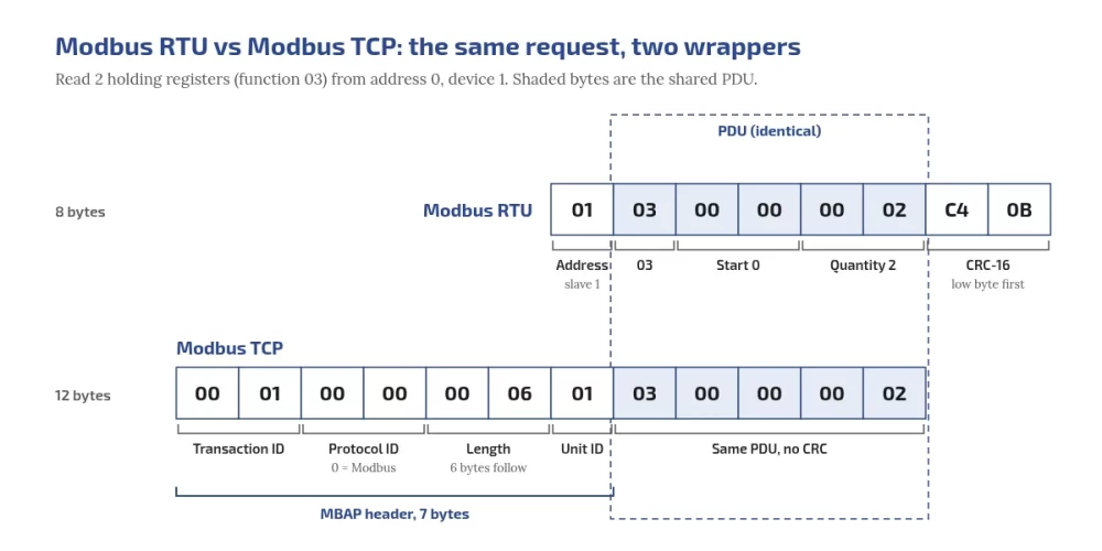
The same request in both formats: read two holding registers (function 03) starting at address 0 from device 1. The specification numbers registers from 1 but addresses them from 0 on the wire. In the common Modicon-style convention many manuals use, holding register 40001 is address 0.

Why do I get exception code 2?

Illegal Data Address. The start address or quantity is outside the device’s map, often because the 40001 offset was not removed.

Embedos blogs diagram of the same Modbus request in two frames. RTU, 8 bytes: 01 slave address, PDU 03 00 00 00 02 (function 03, start address 0, quantity 2), then CRC-16 C4 0B low byte first. TCP, 12 bytes: 7-byte MBAP header 00 01 transaction ID, 00 00 protocol ID, 00 06 length, 01 unit ID, then the same PDU with no CRC. The shared PDU is boxed across both frames.

Modbus RTU request

01 03 00 00 00 02 C4 0B
01     slave address
03     function: read holding registers
00 00  start address 0
00 02  quantity 2
C4 0B  CRC-16, low byte first

Modbus TCP request

00 01 00 00 00 06 01 03 00 00 00 02
00 01  transaction identifier
00 00  protocol identifier (0 = Modbus)
00 06  length: 6 bytes follow
01     unit identifier
03 00 00 00 02  the same PDU, no CRC

The PDU in the middle is identical; only the wrapper changes. Check a Modbus CRC-16 yourself: choose CRC-16/MODBUS and low byte first.

Reading the response: why do floats read wrong?

A 32-bit float needs two 16-bit registers. Modbus sends each register high byte first, but the Modbus application protocol specification does not say which register comes first, so master and device can disagree without any error. A pressure transmitter on a 0 to 50 bar range returns 01 03 04 41 26 66 66 A4 4E over RTU, or 00 01 00 00 00 07 01 03 04 41 26 66 66 over TCP. The two registers are 4126 and 6666 (hex):

Order Bytes Value
ABCD 41 26 66 66 10.4
CDAB (word swapped) 66 66 41 26 2.718 × 10²³
BADC 26 41 66 66 6.710 × 10⁻¹⁶
DCBA 66 66 26 41 2.717 × 10²³

Only ABCD falls inside 0 to 50 bar. These values match the free tool to decode Modbus float word order (ABCD, CDAB).

RTU is a protocol, RS-485 is the wire

Modbus RTU is a framing; RS-485 is the electrical layer it most often runs on. From the Modbus over serial line specification:

  • Addresses: 1 to 247 for slaves, 0 for broadcast, one master at a time.
  • Silent interval: frames are separated by at least 3.5 character times.
  • Devices: 32 devices are always allowed on a segment without a repeater; more only if the device documentation says so. Transceivers rated at a fraction of a unit load raise this. TI’s RS-485 design guide notes that 1/8 unit load parts allow up to 256 nodes on an unbiased bus, but failsafe bias resistors can add up to 20 unit loads, which cuts that to about 96. The Modbus specification likewise reduces the allowed count by 4 when the line is polarised.
  • Trunk length: up to 1000 m at a maximum of 9600 baud with AWG26 or wider cable, halved when 4-wire cable is used as a 2-wire system. Category 5 cable may be used up to 600 m.
  • Drops: derivation cables never more than 20 m. Faster transceivers need shorter stubs, according to the same TI design guide (SLLA272).
  • Termination: at both ends of the trunk only, a 150 ohm resistor, or 120 ohm in series with 1 nF where the line is polarised. Never on a drop, and none on RS-232.
  • Bias (polarisation): one pair of resistors for the whole bus, pull-up to 5 V on D1 and pull-down to common on D0, between 450 and 650 ohm, usually at the master. The specification reduces the allowed device count by 4 when bias is fitted, and 650 ohm allows more devices than 450 ohm.

Check your values with the free RS-485 termination and bias calculator.

Is Modbus RTU the same as RS-485?

No. RTU is the framing and protocol; RS-485 is the electrical layer it usually runs on. RTU can also run on RS-232.

Should I use 8N1 or 8E1?

The specification default is even parity. If you use no parity, it requires 2 stop bits, though many devices ship as 8N1. Match the device.

How many devices can be on a Modbus RTU network?

Addresses run from 1 to 247, but an RS-485 segment is allowed 32 devices without a repeater unless the device documentation permits more, and 4 fewer if the line is polarised.

Speed and polling in practice: which is faster?

On RTU, the arithmetic

At the specification default of 19200 baud, 8 data bits, even parity and 1 stop bit, each byte takes 11 bits, about 0.573 ms. Reading 10 registers from one device:

  1. Request, 8 bytes: about 4.58 ms.
  2. Silent gap of 3.5 characters: about 2.01 ms.
  3. Response, 25 bytes (address, function, byte count, 20 data bytes, CRC): about 14.32 ms.
  4. Another 3.5 character gap: about 2.01 ms.
  5. Total wire time: about 22.9 ms, plus the device’s own response time from its manual.

With 10 such devices on one segment, a full scan takes at least 229 ms plus ten device response times. Above 19200 baud the serial line specification recommends fixed timer values: 1.75 ms for the inter-frame gap (t3.5) and 750 µs for the inter-character time-out (t1.5). Read registers in blocks, up to 125 per request with function 03. If a slave answers only some of the time, rule out clock baud rate error at either end.

On TCP

Wire time is rarely the limit. The device’s response time, how many simultaneous requests it serves, and any gateway in the path, which brings back the serial timing above, decide the real speed. “Faster” depends on the network and the devices, not on the protocol name.

Which is faster, Modbus RTU or Modbus TCP?

The network under TCP is faster, but a slow device answers slowly on either. Gains come from parallel connections, not from the single request.

Ports and security: 502, 802 and authentication

  • Modbus TCP uses registered port 502, as the TCP/IP implementation guide states.
  • Plain Modbus defines no authentication: any client that reaches the port can read and write. NIST SP 800-82 Rev. 3 notes that many OT protocols have no authentication at any level.
  • The Modbus/TCP Security protocol wraps Modbus in TLS, with X.509v3 certificates for authentication and role-based authorisation, on port 802. Check that both ends support it before relying on it.
  • Keep plain Modbus TCP on a segmented OT network, never on the internet.
What port does Modbus TCP use?

Port 502. Modbus/TCP Security, which wraps Modbus in TLS, uses port 802.

Is Modbus TCP secure?

Plain Modbus TCP has no authentication or encryption. Use network segmentation, and Modbus/TCP Security where both ends support it.

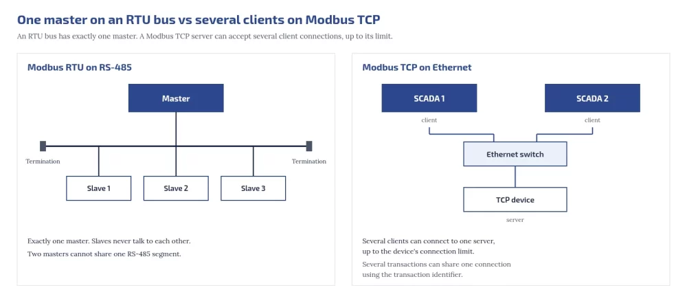
Multiple clients on Modbus TCP vs one master on an RTU bus

An RTU bus has exactly one master, and slaves never talk to each other. Modbus TCP uses a client and server model: the TCP implementation guide lets a server accept several connections and serve several requests at once, up to a limit set by the device’s design, and several transactions can share one connection using the transaction identifier. So two SCADA systems can read one TCP device directly, if the device allows enough connections, but two masters cannot share one RS-485 segment.

embedos-blogs comparison diagram: on the left, a Modbus RTU RS-485 bus with one master, three slaves on short drops and termination at both ends; on the right, two SCADA clients connected through an Ethernet switch to one Modbus TCP server, which accepts several connections up to its limit.
Can Modbus TCP have multiple masters?

Several clients can connect to one server, up to the device’s connection limit. An RTU bus allows only one master.

Modbus RTU over TCP is not Modbus TCP

Some serial device servers forward raw RTU frames, CRC and all, inside a TCP stream, often called “RTU over TCP”. That is not the Modbus TCP format: there is no MBAP header, and framing still depends on the CRC. A Modbus TCP client talking to such a server, or the reverse, gets garbage or timeouts. Set both ends to the same mode.

Converting RTU to TCP: gateways and the Unit Identifier

A Modbus TCP to RTU gateway is a TCP server on the Ethernet side and the single RTU master on the serial side. The TCP implementation guide says the Unit Identifier carries the serial slave address through the gateway; for a device directly on Ethernet it recommends 0xFF. Plan for:

  • requests from several TCP clients being queued and sent one at a time on the serial side;
  • a gateway serial timeout longer than the slowest device’s response, and a client timeout longer still;
  • a table of IP address, Unit Identifier and serial address for every device.

Which one should you choose for your panel?

Situation Usual choice Why
Energy meters or VFDs with only an RS-485 port RTU That is what the device offers; keep the trunk short and terminated
PLC with an Ethernet port and Modbus TCP server TCP No serial wiring; several clients can read it
Many RS-485 devices plus SCADA on Ethernet RTU on the bus, TCP above a gateway Keeps one master per bus
Remote site, few devices, cellular link RTU locally, data sent onward by an edge device Avoids exposing Modbus over the public network

For moving whole machines onto a plant system, OPC UA is often the better upper layer; see our guide to retrofitting legacy machines with OPC UA or Modbus.

Where does Embedos fit?

The Embedos 4G Ethernet Modbus gateway page lists Modbus RTU and Modbus TCP with RS-485, Ethernet, Wi-Fi and 4G interfaces.

Download the Modbus RTU vs TCP Guide

Get the fill-in selection and RS-485 wiring checklist by email. We send the link to your work email.


Decode your registers with the free Modbus register interpreter, and size your bus with the RS-485 termination and bias calculator.

Next step

Polling more than one device? Embedos Edge reads Modbus and pushes it to the cloud. Book a 20 min commissioning call.

Building a new plant? Write these choices into your tenders with our greenfield plant digital readiness checklist.

How to Build an OEE Baseline in Indian Plants Before You Buy an MES


To build an OEE baseline, pick one constraint machine or line, fix the definitions of planned time, ideal cycle time and a good part, then log downtime, output and rejects every shift, by hand if you have to.

Calculate OEE as availability × performance × quality and keep the loss breakdown, because that is what tells you whether MES software will fix anything. Many Indian plants can start with the machines, PLC counters and shift registers they already have.

Who this is for:

Plant heads, process excellence heads and strategy or transformation heads deciding whether and when to buy an MES, and the engineers who will collect the data.

Embedos blogs photo of a large hydraulic forging press with yellow handling equipment on a factory shop floor

What you'll be able to do after reading:

Set up a defensible OEE baseline on one line, read its loss breakdown, and turn it into an MES requirement that vendors must prove against.

What is an OEE baseline, and why do you need one before an MES purchase?

OEE is a measure; an MES is software. NIST IR 7911 describes MES activities as dispatching and executing production orders, collecting production data and analysing production performance. OEE is one of the numbers that analysis produces. In the ISA-95 model, MES sits at Level 3, manufacturing operations management. An OEE baseline is that number, with its three factors and its losses, measured the same way over a fixed period before anything changes. For a general definition, Wikipedia’s article on overall equipment effectiveness is useful further reading.

Without a baseline, an MES project has no yardstick. With one, you can ask a vendor which of your losses their system recovers and check the answer later against your own locked figure.

We don’t trust our current OEE numbers. Where do we start?

Start with definitions, not software. Most distrusted OEE numbers are calculated correctly from inputs that mean different things on different shifts:

  • Planned time is not fixed. One shift deducts tea breaks and the weekly PM, another does not.
  • The ideal cycle time is today’s average. That hides every slow cycle and makes performance look close to 100%.
  • Short stops are never written down. A two-minute jam that happens thirty times a shift is invisible in a log that only records breakdowns.
  • Rework is counted as good. The ISO 22400-2 quality rate counts only parts that were right the first time.
  • Machines are averaged. A simple average of five machines’ OEE says nothing about the line’s output.
What is the difference between OEE and MES?

OEE is a performance measure. An MES is software that runs and records production, and it can calculate OEE among many other things.

How do you calculate OEE for a machine?

NIST AMS 300-11 defines OEE as the product of availability, performance and quality. ISO 22400-2, the international standard for manufacturing KPIs, uses the same structure; the full ISO text is a paid document. A free paper by Kang and colleagues, hosted by NIST, explains the ISO 22400 time and quantity elements behind these formulas. We use the ISO 22400-2 quality rate, which counts only good parts and excludes rework. The NIST paper itself uses a “quality buy rate” that counts reworked parts as good, so check which definition a vendor uses.

Factor Formula Loss it shows
Availability Actual run time ÷ planned busy time Breakdowns, changeovers, waiting for material or operators
Performance (Ideal cycle time × total count) ÷ actual run time Slow cycles and short stops
Quality Good count ÷ total count Scrap and rework

A shortcut gives the same answer: good count × ideal cycle time ÷ planned busy time. If your two methods disagree, an input is wrong.

Worked example: one shift by hand

These numbers are illustrative, not a benchmark.

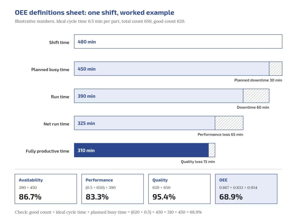
Embedos blogs diagram of OEE shift time losses for one illustrative shift: shift time 480 min minus 30 min planned downtime gives planned busy time 450 min; minus 60 min downtime gives run time 390 min; minus 65 min performance loss gives 325 min; minus 15 min quality loss gives 310 min fully productive time. Availability 390 ÷ 450 = 86.7%, performance (0.5 × 650) ÷ 390 = 83.3%, quality 620 ÷ 650 = 95.4%, OEE 68.9%.
  1. Shift length 480 minutes, with a 30 minute planned break. Planned busy time = 450 minutes.
  2. Logged unplanned downtime 60 minutes. Actual run time = 450 − 60 = 390 minutes.
  3. Ideal cycle time 30 seconds (0.5 minute) per part. Total count 650 parts. Good count 620 parts.
  4. Availability = 390 ÷ 450 = 86.7%.
  5. Performance = (0.5 × 650) ÷ 390 = 325 ÷ 390 = 83.3%.
  6. Quality = 620 ÷ 650 = 95.4%.
  7. OEE = 0.867 × 0.833 × 0.954 = 68.9%. Check: (620 × 0.5) ÷ 450 = 310 ÷ 450 = 68.9%.
Bucket Minutes How it is worked out
Availability loss 60 Unplanned downtime
Performance loss 65 390 run minutes − 325 minutes of ideal production
Quality loss 15 30 bad parts × 0.5 minute
Fully productive time 310 620 good parts × 0.5 minute
Total 450 Equals planned busy time

Here the biggest loss is speed, not breakdowns. A downtime-reason screen alone would not recover those 65 minutes, which is exactly the kind of finding that should shape an MES requirement.

Which definitions do you lock first: planned downtime, ideal cycle time and good parts?

  • Planned downtime. In the ISO 22400 elements explained in the NIST paper, planned operation time = planned busy time + planned downtime, and planned downtime includes scheduled breaks, meetings and maintenance. So planned downtime comes out before availability is calculated. Decide what counts as planned and write it down.
  • Ideal cycle time. Use the validated or nameplate cycle time per product, not the usual average. If performance comes out above 100%, the ideal cycle time has been set too long (too slow), or a count is wrong.
  • Good part. Right first time only. Count rework separately.
  • Downtime reasons. A short list, ideally under ten, plus “other”.

Get production, maintenance and quality to sign this one-page sheet before collecting data.

Does OEE include planned downtime?

In the ISO 22400 elements explained by NIST, planned downtime is removed before availability is calculated. Some plants include it; either works if written down and kept fixed.

Can OEE be more than 100%?

Not with correct inputs. Above 100% usually means the ideal cycle time is set too long, or a count is wrong.

Who should own the baseline?

Production or process engineering, with maintenance and quality signing the definitions. IT supports the data.

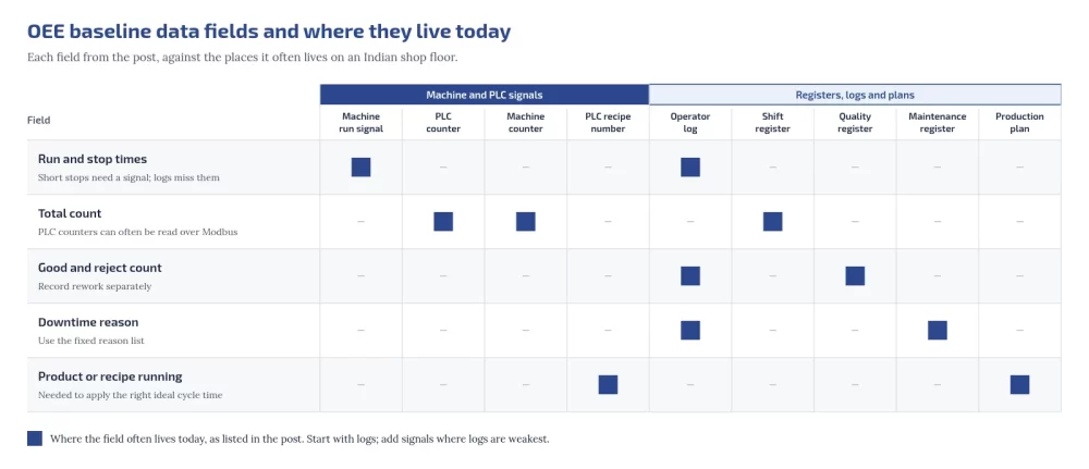
Which data fields do you collect, and where do they live on an Indian shop floor?

Field Where it often lives today Notes
Run and stop times Machine run signal, operator log Short stops need a signal; logs miss them
Total count PLC counter, machine counter, shift register PLC counters can often be read over Modbus
Good and reject count Quality register, operator log Record rework separately
Downtime reason Operator log, maintenance register Use the fixed reason list
Product or recipe running Production plan, PLC recipe number Needed to apply the right ideal cycle time

If a PLC counter is reachable, you can decode PLC counter registers with a free tool. Where a sensor signal stands in for a run state, for example a motor current transmitter, you may need to scale 4-20 mA signals correctly.

embedos-blogs matrix of OEE baseline data fields against where they often live today: run and stop times in the machine run signal and operator log; total count in the PLC counter, machine counter and shift register; good and reject count in the quality register and operator log; downtime reason in the operator log and maintenance register; product or recipe running in the production plan and PLC recipe number.

Can we baseline with manual logs, or do we need sensors first?

Method Effort to start Captures well Misses
Manual shift log Low Long stops, reasons, scrap Short stops, exact times
Manual log plus run/stop and count signals Moderate Exact run time, counts, short stops Reasons, unless operators tag them
Full MES High All of the above plus orders and quality steps Nothing in scope, if adopted

Start with logs; add signals where logs are weakest. Older machines may need a retrofit to give a run signal.

Which machines do we baseline first?

  • The constraint, the machine that sets the line’s output.
  • The machine your MES business case leans on most.
  • A machine where the shift team is willing to log honestly.
  • A machine where a run/stop signal is easy to reach.
Which data fields are essential to collect for OEE?

Planned busy time, unplanned downtime, ideal cycle time, total count and good count, plus the product running and downtime reasons.

Do we need to stop production to set up a baseline?

No. Manual logging needs no downtime. Adding a run/stop signal may need a short electrical job, which can go into an existing planned stop.

How long should you measure, and what do you exclude?

No standard fixes a baseline length, so a fixed number of days, 30 or any other, is a choice rather than a rule. A baseline means something once it covers your plant’s normal variation:

  • every shift and crew, including night shift;
  • at least one full cycle of your product mix and changeover types;
  • your usual maintenance pattern;
  • a weekly figure that has stopped moving much from week to week.

Exclude only what your definitions sheet excludes, such as declared planned downtime, and note one-off events (a power cut, a trial run) separately rather than deleting them. Historical data can serve as a baseline only if it was recorded with the same definitions; otherwise treat it as indicative and start a fresh log.

Can I use historical data as a baseline?

Only if it was recorded with the same definitions you will use later. Otherwise use it as a rough guide and start a clean log.

Embedos blogs photo of a 16,000 kN transfer press in a press shop hall, with an operator standing beside it

What is a good OEE number, and why not compare with “world class” figures?

ISO 22400 defines how to calculate OEE, not what it should be. Published “world class” figures come from different sources, industries and definitions, and none is set by a standard. Your baseline is only comparable with itself, measured the same way later.

What is a good OEE score in manufacturing?

There is no standard target. ISO 22400 defines the calculation, not a goal. Compare a machine against its own baseline.

How do you turn the baseline into an MES requirement and vendor scorecard?

Lock the baseline and give every vendor the same one-page summary: OEE, the three factors and minutes lost per bucket. Then score proposals like this:

Ask the vendor What good evidence looks like
Which of our loss buckets does your system address, and how? A specific mechanism per bucket, not a general percentage
Will you calculate OEE with our signed definitions? Yes, including the ISO 22400-2 quality rate without rework
How will you prove the improvement? Measured against our locked baseline, same definitions, same machines
What data do you need from our machines and ERP? A signal list and an integration plan, see MES vs ERP

How does a baseline compare in effort with a full MES?

A baseline needs a definitions sheet, a log, a spreadsheet and, at most, a few signals. An MES needs product and routing master data, an ERP integration, operator workflows, training and change management. The baseline fits inside one department, and it tells you whether the bigger project is aimed at your real losses. Planning a new plant instead? Put the same definitions into your greenfield plant digital readiness checklist.

Is the baseline wasted if we buy an MES later?

No. The definitions, downtime reasons and baseline figures become the MES configuration and the yardstick for judging it.

Where does Embedos fit?

For the baseline period, the hard part is often getting run and count signals off older machines. The Embedos Edge page describes the device as capturing machine and sensor data and sending it to cloud storage or a factory control room. Our pages on plant KPI dashboards for leadership and shift-level visibility for plant managers describe how we approach this.

Download the OEE Baseline Kit

Get the fill-in checklist by email. We send the link to your work email.


Next step

Want a clean OEE baseline on one line before you commit to an MES? We run a fixed-scope POC in one department. Email team@embedos.io to discuss an OEE baseline POC.

How do you keep proving data center noise compliance after the site is built?

To keep proving compliance, an operating data center needs continuous boundary logging that compares day and night Leq with the CPCB zone limits (CPCB Noise Rules 2000) while chillers, dry coolers and DG tests change the plant from hour to hour.

Log at fixed property line points facing the nearest receptors, tag every record with plant state, and keep the raw data ready for a complaint.

Who this is for: facility managers, EHS leads, community liaison staff and consultants supporting an operating data center in India.

Hub: where data center noise comes from.

Tell us what you need on site

Need this on your site? Tell us your requirement

One survey vs continuous compliance: what each is for

A snapshot answers one question at one time. It is the right tool for an acceptance test after commissioning, an annual check, or an attended visit after a complaint. It is usually done with a Class 1 meter, an operator on site, and a written report.

A continuous program answers a different question: does the site stay inside its limits on every night of the year, including the nights when two chillers are on and the DG is under test? It uses permanent or long-term loggers, covers both the day and night windows, and raises alarms before neighbours notice.

You need both. The prediction work belongs in predicting night noise before you build, and meter class, Leq, L90 and spectra are covered in Class 1 vs Class 2 sound level meters. This post covers what happens after handover.

Is a post-construction noise study enough for compliance?

It is a necessary first step, not the end. A post-construction study proves the site met its limits on the days it was measured, with the plant state of those days. Cooling load, weather, equipment wear and DG test schedules all change later, so ongoing logs are what show the result still holds.

What changes after the data center is live

The plant you predicted is not the plant you run.

  • Cooling stages with IT load and weather. More fans and compressors run on hot afternoons and as halls fill. See how cooling plant noise changes with load.
  • DG testing is intermittent and loud. A monthly or weekly test can dominate a boundary reading for its duration.
  • Failures shift load. When one fan fails, the others in the bank speed up, and the level and tone at the fence change.
  • Night ambient drops. Road and city background falls after 10:00 p.m., so the same plant is easier to hear at night.

Outside India, some local authorities now write post-construction studies, recurring tests or permanent boundary monitors into data center approvals. One example is the Fairfax County data center noise study requirements ( foreign context only, not an Indian rule). In India the compliance frame is the CPCB ambient schedule plus any condition in your own consent.

Why do data centers need continuous noise monitoring?

Because the noise changes all the time. Cooling plant follows load and weather, DG tests come and go, and night background is lower. One reading cannot show all of those states. Continuous logs show trends, catch step changes early and give you a record when someone asks.

Which numbers the continuous log must compare against

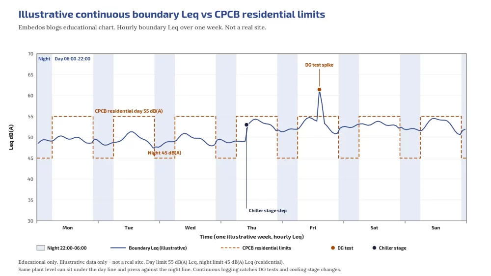
The Noise Pollution (Regulation and Control) Rules, 2000 set ambient limits in dB(A) Leq by zone (CPCB C1, Delhi Noise Limit

Zone Day Leq dB(A) Night Leq dB(A) Night is lower by
Industrial 75 70 5 dB
Commercial 65 55 10 dB
Residential 55 45 10 dB
Silence zone 50 40 10 dB

Day is 6:00 a.m. to 10:00 p.m. and night is 10:00 p.m. to 6:00 a.m. A silence zone covers not less than 100 m around hospitals, educational institutions and courts, as declared by the State Government. Rule 7(1) lets a person complain when the ambient standard is exceeded by 10 dB(A) or more, or when night restrictions are broken.

DG sets have a separate product limit. New sets up to 1000 kVA made on or after 1 January 2005 must not exceed 75 dB(A) at 1 m from the enclosure, and user-end enclosures and exhaust mufflers need at least 25 dB(A) insertion loss, or must meet the ambient standard, whichever is higher (CPCB DG noise limits C2 ; Delhi noise limit).

That limit sits at the set. Your boundary log is judged against the ambient table above. This is not legal advice; confirm the zone category and any consent condition with your consultant or SPCB.

What are the CPCB day and night ambient noise limits?

Industrial 75 day and 70 night, commercial 65 and 55, residential 55 and 45, silence zone 50 and 40, all in dB(A) Leq. Day runs 6:00 a.m. to 10:00 p.m. and night runs 10:00 p.m. to 6:00 a.m. Night is 5 dB lower in industrial areas and 10 dB lower in the other zones.

Embedos blogs embedos-blogs-continuous-boundary-log-day-night-cpcb-embedos: week of hourly boundary Leq against CPCB residential 55 day and 45 night lines

Post-construction check first, then the ongoing program

Start with one careful attended check once the site runs near its design load.

  1. Measure at the same boundary and receptor points used in the baseline, so results line up.
  2. Record plant state for every interval: chiller and dry cooler stages, DG on or off, IT load band.
  3. Cover both windows. A daytime pass alone tells you little about the 45 dB(A) residential night limit.
  4. Compare with the prediction from the impact assessment. Large gaps point to a source or path the model missed.
  5. Choose the permanent points for continuous logging from what you learned.

There is no Indian rule we can point to that makes a permanent boundary monitor mandatory for every data center. Some US ordinances ask for one; treat that as context, and check your own consent or SPCB conditions with your consultant. Many operators keep continuous logs anyway because they are the fastest way to answer questions.

How often should noise be checked after a data center starts up?

Do an attended check after startup at near design load, then keep continuous logs at the boundary. Add an attended Class 1 check after any major cooling or DG change, after a complaint, and on whatever schedule your consent or SPCB condition sets. US annual retest rules are context only.

Where to place permanent or long-term boundary monitors

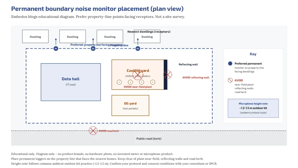
  • Facing receptors. Put points on the property line facing the nearest dwellings, schools, hospitals or other silence zone receptors.
  • Out of the near field. A monitor next to a dry cooler measures the dry cooler, not the community exposure.
  • Height and weather. Follow the ambient protocol for microphone height and use an outdoor kit with windscreen and rain protection (CPCB Protocol for Ambient Level Noise Monitoring, MPCB host).
  • Avoid reflections and roads. Keep away from hard walls and road kerbs that would dominate the reading.
  • Power and access. A point you cannot service is a point that stops logging.

Embedos blogs embedos-blogs-permanent-boundary-noise-monitor-placement-embedos: plan view preferred permanent boundary monitors facing dwellings, avoid near-field plant

Where should permanent noise monitors sit at a data center?

On the property line facing the nearest receptors, away from the plant near field, at the height the ambient protocol sets, with outdoor weather protection and clear of reflecting walls and busy roads.

What a compliance-ready continuous log must capture

  • Time-stamped Leq for each hour, rolled up to the day and night windows.
  • L90 or a similar background descriptor, so you can separate plant from road.
  • dB(A) plus dB(C) or octave bands when tonal hum is the complaint. See why dBA can miss low frequency hum.
  • Meter make, serial number, class and calibration dates.
  • Weather notes: wind, rain, temperature.
  • Plant tags at the same timestamps: DG run, chiller or dry cooler stage, IT load band.
  • Raw exportable records kept for as long as your consent or legal advisor recommends.

The CPCB ambient protocol describes supervised sessions with 1 second sampling and day or night coverage for routine and complaint work. A permanent station extends that idea across weeks and months, and attended sessions still matter when a result is disputed.

What should a data center boundary noise log include?

Hourly Leq rolled into day and night windows, a background descriptor such as L90, dB(C) or bands for tonal issues, meter serial and calibration, weather, and plant state tags at the same timestamps. Keep the raw records.

Alarms that help operations before neighbours call

Useful alarms are simple:

  • Night margin. Rolling night Leq within a few dB of the zone limit.
  • Step change. A jump at one point that matches a fan bank going to high speed or a failed unit.
  • DG window. Flag test periods so readings are explained, and move tests into daytime where you can.
  • Data gap. A logger that stops is its own alarm.

Alarms are operational aids. They are not a legal finding, and the thresholds are yours to set. We do not quote fine amounts here; any penalty question belongs with your legal advisor and the SPCB.

Answering a neighbour or authority complaint with the log

  1. Acknowledge the complaint and note the date, time and location described.
  2. Pull the boundary traces for that window, plus the nearest façade point if you have one.
  3. Show plant state at the same timestamps.
  4. Compare the night or day Leq with the CPCB zone limit.
  5. Check tonal content if the words were hum, drone or throb.
  6. Fix source or path: fans and controls first (cooling plant), then barriers and enclosures when the log shows a path problem.
  7. Re-measure with an attended Class 1 check and share the before and after.

For why night levels matter to people living nearby, see health framing for neighbours. Night guidance from WHO Europe sets 40 dB Lnight outside as a target and 55 dB as an interim target (WHO Night Noise Guidelines 2009).

We make no health claim for any Embedos product.

How do you answer a data center noise complaint with data?

Pull the boundary log for the complaint window, show plant state, compare with the CPCB zone limit, check for tones, fix the source or path, then confirm with an attended Class 1 measurement.

Checklist: continuous compliance program for an operating Indian site

# Item Done
1 Zone category confirmed for each receptor (industrial, commercial, residential, silence) ☐
2 Post-startup attended check done at near design load, day and night ☐
3 Permanent boundary points chosen facing receptors, out of near field ☐
4 Meters: Class 1, or Class 2 stated as screening, with outdoor kit ☐
5 Day and night Leq plus L90 logged and retained ☐
6 Calibration schedule and field calibrator checks recorded ☐
7 Plant state tags (DG, cooling stages, IT load band) on the same timeline ☐
8 Alarm thresholds set for night margin, step change, data gap ☐
9 Complaint pack template ready ☐
10 Review after any major cooling or DG change ☐

Writing noise limits into purchases helps too: see writing noise limits into equipment tenders so the plant starts quieter. Inside the hall is a separate exposure problem: staff hearing in the data hall.

Can continuous logging replace a Class 1 attended survey?

No. Continuous logging is best for trends, alarms and answering “what happened that night”. An attended Class 1 survey, with a calibrated meter and an operator who can note what is audible, is what you bring to a dispute or a formal report.

Automation angle: third-party meter into Embedos Edge

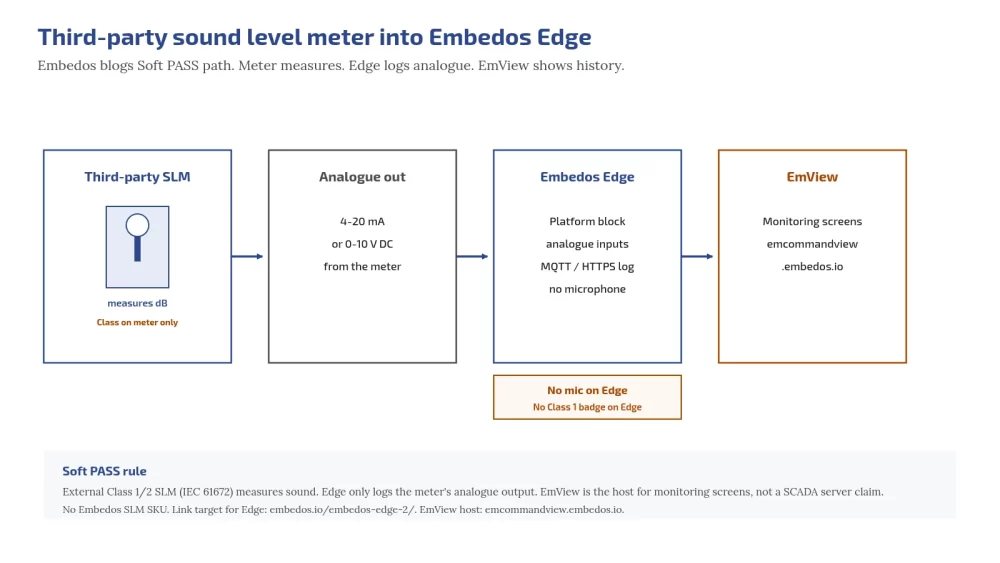
A Class 1 or Class 2 sound level meter or noise recorder (IEC 61672, a paid standard) with an analogue output can be wired to an analogue input on Embedos Edge, using 4-20 mA or 0-10 V.

The Embedos Edge is the platform that logs that signal day and night, next to DG run and cooling stage status, and can raise an alarm when the night margin is at risk.

The Embedos Edge has no microphone of its own and does not measure sound by itself; the class belongs to the meter. Edge makes no compliance or health judgement.

To check how a meter’s range maps onto a 4-20 mA loop, try the 4-20 mA loop scaling calculator.

If a hosted view is needed, monitoring screens sign in at EmCommandView.

Embedos blogs embedos-blogs-slm-analogue-to-edge-embedos: third-party sound level meter analogue output 4-20 mA or 0-10 V into Embedos Edge platform, optional EmCommandView screens

Next step

Send us your site plan, receptor locations and meter model, and we will help you plan boundary logging points and the analogue wiring into Edge.

Email: team@embedos.io

Help Us Help You Leverage The Power Of Industrial Automation & Industrial IoT – IIoT.
Retrofitting Legacy Machines and PLCs with OPC UA or Modbus

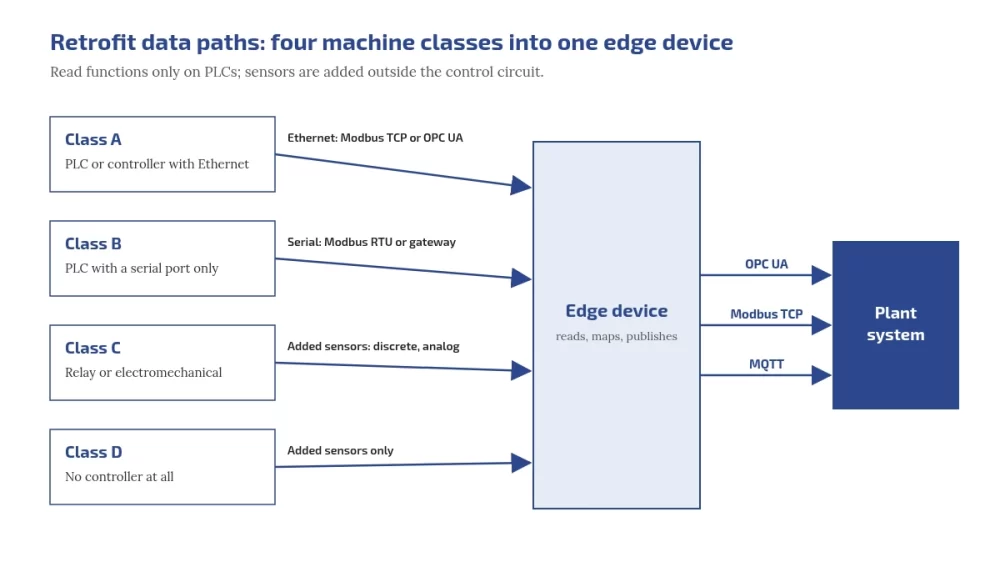
You can retrofit legacy machines without touching their control logic. Classify each machine first: PLC with Ethernet, PLC with serial only, relay or electromechanical, or no controller at all. Then read the PLC over Modbus or OPC UA using read functions only, or add sensors outside the control circuit where there is no usable PLC. Publish everything upwards through open protocols, and use OPC UA where you need structure and security that plain Modbus does not give.

Who this is for:

Plant heads deciding between retrofit and replacement, and the maintenance and automation engineers who have to connect mixed-age machines and older PLCs.

Embedos blogs photo of an older centre lathe in a working metal workshop, beside a staircase and waste bins

What you'll be able to do after reading:

Classify your machines, choose Modbus, OPC UA or added sensors per machine, map Modbus registers to OPC UA variables, plan a first retrofit that cannot write to a PLC, and judge when to replace instead.

Why retrofit before you replace?

A machine that still makes good parts usually has years of mechanical life left even when its controls are old. Retrofitting adds data without changing how the machine runs, so it costs a fraction of a replacement in money and downtime and can start on one machine. Replacement makes sense when spares, support or safety, not data, are the problem; the questions for that decision are further down.

Step 1: classify every machine

ClassWhat it hasTypical data path
APLC or controller with EthernetModbus TCP, or the controller’s OPC UA server if it has one
BPLC with a serial port onlyModbus RTU if the PLC can act as a Modbus slave, or a protocol gateway
CRelay or electromechanical controlsDiscrete and analog signals from added sensors
DNo controller at allAdded sensors only

Walk the floor with this table: note panel space, nameplates, existing ports and spare terminals for each machine. A closed controller with no documentation goes into class C or D, even if it has a port.

Step 2: choose the data path per class

PointAdded sensors (current, 4 to 20 mA, RTD, counts)Reading the PLC (Modbus or OPC UA)
Touches the control systemNo, if mounted outside the control circuitA connection to its communication port, configured to use read functions only
Signals availableOnly what you measureEverything the PLC knows, if documented
Downtime reasonsOperators tag themAlarm and fault codes, if mapped
Dependence on the machine builderLowHigher: you need the memory map or tag list
Best forClasses C and D, quick uniform run and idle dataClasses A and B with documented controllers

How do you connect a PLC to the internet or cloud?

Not directly. CISA’s first OT mitigation is to remove OT connections to the public internet. Connect the PLC to an edge device on the OT network; the edge device reads it and sends data onward over a controlled, outbound route.

Can we use the machine's existing sensors?

Sometimes, through the PLC. Splitting an existing analog signal can disturb the control loop, so add a separate sensor when in doubt.

Embedos blogs diagram of four machine classes feeding one edge device: Class A PLC with Ethernet over Modbus TCP or OPC UA, Class B PLC with serial port only over Modbus RTU or a gateway, Class C relay or electromechanical controls through added discrete and analog sensors, Class D with no controller through added sensors only. The edge device publishes OPC UA, Modbus TCP and MQTT to the plant system.

Worked example: scaling a 4 to 20 mA signal

A pressure transmitter on a 0 to 10 bar range, a 150 ohm sense resistor, and a 12-bit ADC with a 3.3 V reference. The loop reads 12.6 mA. These numbers match the free tool to scale 4-20 mA signals from relay-era machines.

  1. Sense voltage = 12.6 mA × 150 ohm = 1.890 V.
  2. ADC counts = (1.890 ÷ 3.3) × 4095 = 2345.
  3. Process value = 0 + ((12.6 − 4) ÷ 16) × 10 = 5.375 bar.
  4. At 4 mA the ADC reads 745 counts, at 20 mA 3723 counts, so resolution is about 0.0034 bar per count.
  5. At or below 3.6 mA, or at or above 21 mA, NAMUR NE 43 treats the signal as a failure, for example a transmitter fault or a broken wire, so alarm on it instead of showing 0 bar. Readings from 3.8 to 4.0 mA and 20.0 to 20.5 mA are still valid, just under or over range. NE 43 itself is a paid NAMUR document; Beckhoff’s documentation summarises its limits.

A 250 ohm resistor puts 20 mA at 5 V, which clips a 3.3 V ADC. For ovens, dryers and moulds, check temperature readings with the RTD PT100 and PT1000 calculator, including the error a 2-wire RTD adds through its leads.

What does OPC UA add over Modbus?

PointModbusOPC UA
Data modelNumbered registers and coils; meaning lives in a separate documentNamed, typed nodes in an information model that clients can browse, as the OPC UA overview describes
Machine descriptionNoneCompanion specifications such as OPC 40001-1 Machinery: identification, state, counters
SecurityNone in plain Modbus; Modbus/TCP Security adds TLS on port 802Built in: application authentication, signing and encryption, per the OPC UA security model
Typical role in a retrofitReading old devicesPublishing structured data upwards

OPC UA is an open, royalty-free set of standards from the OPC Foundation, as the Machinery specification notes, and the full specifications are free to read online. So the usual answer to “OPC UA vs Modbus” in a retrofit is both: Modbus at the bottom, OPC UA at the top. The OPC Foundation also publishes an open-source edge application, UA Edge Translator, that translates other protocols into OPC UA.

Download the Free “Legacy Machine Retrofit Playbook (Checklist)”!


What is OPC UA used for?

Exchanging industrial data between machines, controllers and plant or business systems, with an information model and built-in security.

OPC UA vs Modbus: which should I use?

Modbus is often all an old device speaks. OPC UA is better for publishing structured, secured data upwards. Many retrofits use both.

Is OPC UA secure, and is it free?

Its security model includes authentication, signing and encryption. The standards are royalty free and readable online, and the OPC Foundation publishes open-source code.

Modbus to OPC UA gateways: mapping registers to variables

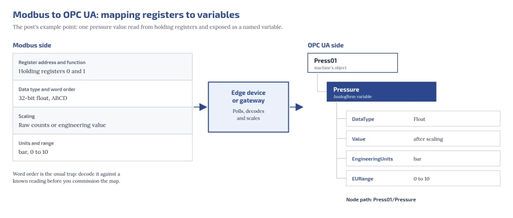
An edge device or gateway polls Modbus and exposes each value as an OPC UA variable. For every point, define:

Modbus sideOPC UA sideExample
Register address and functionNode name under the machine’s objectHolding registers 0 and 1 → Press01/Pressure
Data type and word orderDataType32-bit float, ABCD → Float
ScalingValue after scalingRaw counts or engineering value
Units and rangeEngineeringUnits and EURange of an AnalogItembar, 0 to 10

Wikipedia’s OPC Unified Architecture article is useful further reading on OPC UA itself. Word order is the usual trap: decode Modbus float word order against a known reading before you commission the map. For the transport underneath, see Modbus RTU vs Modbus TCP.

embedos-blogs diagram mapping a Modbus point to an OPC UA variable: holding registers 0 and 1, 32-bit float with ABCD word order, scaling, and bar with a range of 0 to 10 pass through an edge device or gateway that polls, decodes and scales them into the AnalogItem variable Press01/Pressure with DataType Float, a scaled value, EngineeringUnits bar and EURange 0 to 10.
How does a Modbus to OPC UA gateway work?

It polls Modbus registers, decodes and scales them, and exposes each as a named OPC UA variable with type and units.

Start with read functions only

Modbus has no read-only mode, and OPC UA has none by default: any client that reaches the port can send write function codes (05, 06, 15 and 16 in the Modbus application protocol specification) unless something blocks them. So “read-only” is a configuration the integrator must enforce: disable or block write function codes in the edge device or gateway, and do not enable writes until change control is in place. NIST SP 800-82 Rev. 3 and CISA’s OT mitigations also call for segmenting IT and OT networks, changing default passwords and securing remote access.

Do we need OEM permission, and does it affect the warranty?

  • Sensors outside the control circuit do not change how the machine runs. Still inform the OEM while under warranty.
  • A connection to an existing communication port that is configured to use only read functions does not change the PLC program. Disable or block write function codes in the edge device or gateway, but the OEM may still need to tell you the settings and memory map.
  • Any change to the PLC program, safety circuits or control wiring needs written OEM approval while under warranty. Do not do it for monitoring. Check your contract in every case.

What happens to production during the install?

  1. Survey while the machine runs.
  2. Prepare and test the edge device and configuration off the machine.
  3. Install sensors and cabling during an existing planned stop.
  4. Connect to the PLC with write function codes blocked at the edge device, and confirm the HMI and control behave as before.
  5. Run in parallel with manual logs until the numbers agree.
Should a retrofit start read-only?

Yes, in practice: block write function codes at the edge device or gateway, because neither Modbus nor OPC UA is read-only by default.

Embedos blogs photo of a Siemens Simatic S7-300 PLC with CPU and I/O modules on a mounting rail

A pilot plan: one line, a fixed window, clear measures

  1. Pick one line, including its constraint machine.
  2. Agree the window in advance and do not move it.
  3. Measure run state, part counts, downtime with reasons, and one or two process values that explain quality.
  4. Compare against manual logs, then use the data for an OEE baseline.
  5. Decide the next line only once the first line’s numbers are trusted.
How many signals per machine should we start with?

Run state and part count. Add process values only where they explain quality or downtime.

Retrofit vs replace: questions for the plant head

  • Are spares for the controller still available, and from whom?
  • Does the OEM still support the controller and its software?
  • Is the problem missing data, or unreliable control and safety?
  • How much downtime would a replacement need, and when could the plant afford it?
  • Will a retrofit now still be useful if the controller is replaced later?

Will a retrofit lock us into one vendor?

It does not have to. Put these in the order: data published over open protocols such as OPC UA, Modbus TCP or MQTT; raw data exportable in an open format such as CSV without a licence fee; full tag documentation; standard signals (4 to 20 mA, RTD, 24 V digital); and configuration backups handed to the plant.

Who should own the retrofit?

Maintenance or automation engineering for the hardware, with production agreeing what the data must answer.

Where does Embedos fit?

The Embedos Edge IoT gateway page lists Modbus RTU, Modbus TCP, CAN bus and OPC UA among supported protocols, and MQTT, HTTP and HTTPS for sending data onward. Our page on connecting PLCs and controllers describes how we work with automation engineers. For a new plant, put connectivity in the tenders instead, with the greenfield plant digital readiness checklist.

For engineers: check your loop scaling with the free 4 to 20 mA loop scaling calculator and your temperature readings with the RTD PT100 and PT1000 calculator.


Next step

Logging these sensors across the plant? Embedos Edge takes analog and digital I/O. Book a 20 min commissioning call.

Connecting this machine to your plant system? We build OPC UA links end to end. Email team@embedos.io about OPC UA integration.