
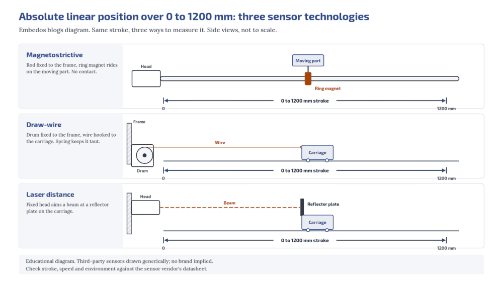
An absolute linear position sensor over 0 to 1200 mm, the usual shortlist is:
A magnetostrictive sensor (non-contact, mounted in a hydraulic cylinder or as an external profile),
or
A draw-wire sensor (a spring-loaded wire on a drum turning an absolute encoder or potentiometer)
or
A laser distance sensor (non-contact, needs a clear line of sight).
Potentiometric rod sensors suit shorter strokes, and LVDTs are mostly used for short strokes.
“Absolute” means the sensor reports the true position at power-up, with no homing run.
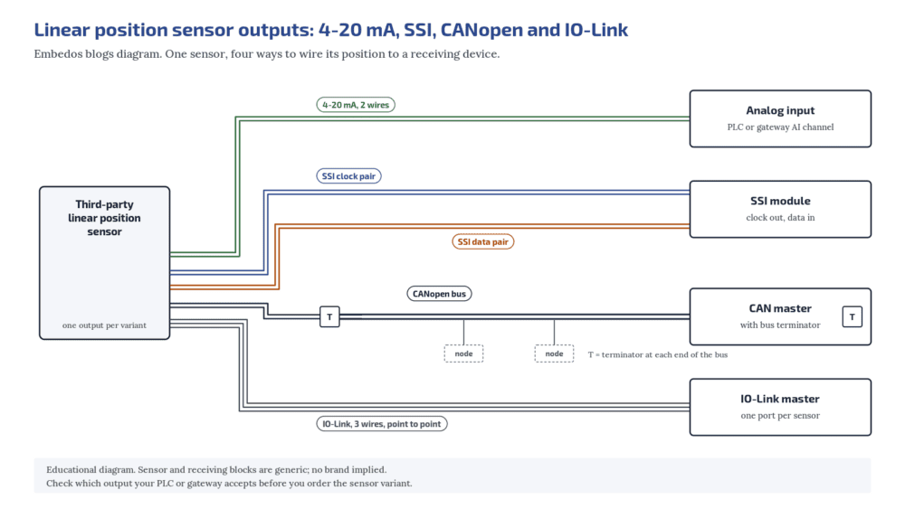
For the output, choose by what the PLC can take: 4-20 mA is the simplest and works with any analog input; SSI gives a digital absolute value over a differential line to a PLC with an SSI interface; CANopen and IO-Link need a matching master.
When selecting, search for ddetails around stroke, resolution, speed, mounting and output, not around one technology name.
Who this is for: instrumentation, hydraulics and automation engineers in steel plants and heavy industry writing a tender or replacing a position sensor on a cylinder, gate, roll gap, carriage or damper.
What “absolute” means, and why manufacturing companies ask for it?
An incremental sensor counts pulses from a reference point. After a power cut, it has to be driven to a home position before the reading means anything.
An absolute sensor gives the real position as soon as it powers up.
On a hydraulic cylinder, a gate or a roll gap, homing after every power dip costs time and can be unsafe. That is why tenders specify absolute sensing.
The magnetostrictive principle, for example, gives an output that corresponds to absolute position and does not need re-homing after a power loss.
Potentiometric sensors also give an absolute output after power loss.
Draw-wire sensors are absolute only when the drum drives an absolute encoder or a potentiometer, not an incremental encoder.
Magnetostrictive sensors
A magnet rides on the moving part, outside a rod or profile that holds a ferromagnetic waveguide.
The electronics send a short current pulse down the waveguide.
Where the pulse’s field meets the magnet’s field, a torsional strain pulse starts and travels back to the sensor head at a known speed.
The travel time gives the position.
Why they suit 0 to 1200 mm. There is no contact between the magnet and the sensing element, so nothing wears.
Rod styles fit inside a gun-drilled hydraulic cylinder piston rod, which protects the sensor from the plant environment, and profile styles mount outside a machine. Catalogue stroke ranges for this type run well beyond 1200 mm.
Some datasheets lists profile and rod strokes in the metres.
What to check. Stroke and the dead zones at each end, the magnet type and how it is mounted, cylinder bore and pressure rating for rod styles, the output and update time, and the temperature at the sensor head.
Draw-wire sensors
How they work. A flexible steel wire is wound on a constant-diameter drum held under tension by a spring. The sensor body is fixed; the wire end hooks to the moving part.
As the part moves, the drum turns a potentiometer or an encoder, giving an output proportional to the wire extension.
Why they suit 0 to 1200 mm. They are compact for the stroke and easy to retrofit, because the body mounts at one point and only the wire end attaches to the moving part.
What to check. The reel mechanism limits how fast the target can move. Temperature changes affect the wire length and a potentiometer’s resistance. Keep the wire path clear of scale, sharp edges and anything that could snag it, and protect the drum from dust and water.
Confirm the variant is absolute.
Potentiometric rod sensors
How they work. A wiper on the rod slides along a conductive plastic resistance track. With a supply across the track, the wiper voltage is proportional to position, and the output stays absolute after power loss.
The wiper should feed a high-impedance input; the LWG datasheet linked below recommends a wiper current of no more than 1 µA.
Fit for 0 to 1200 mm. Check the vendor’s stroke range first. One pivot-head series, for example, is listed up to 750 mm (Novotechnik LWG datasheet), which is short of a 1200 mm stroke.
The wiper is a contacting part, so consider cycle life on a fast, continuously moving axis.
Can an LVDT measure 1200 mm?
Rarely. Most catalogue LVDTs cover a few millimetres to a few hundred, and the longest reach about ±500 mm with a body well over a metre long. For 1200 mm, look at magnetostrictive, draw-wire or laser sensors first.
LVDTs
A Linear Variable Differential Transformer (LVDT) is a displacement sensor. It has a primary coil and two secondary coils around a movable soft-magnetic core.
An oscillator drives the primary; as the core moves, the voltage rises in one secondary and falls in the other, and the difference is proportional to displacement.
They are non-contact and well proven.
They need AC excitation and a demodulating conditioner, which DC-operated models build in. Common catalogue ranges are short: the Micro-Epsilon manual covers ±1 to ±25 mm.
Long-stroke LVDTs exist, with one maker listing up to ±500 mm (Messotron DGO), but the body is longer than the full stroke (1420 mm installed for ±500 mm). For 1200 mm, look at the other types first.
Laser distance sensors
A laser distance sensor measures to a target plate or surface on the moving part without touching it.
Long-range models are sold for cranes and for positioning hot steel slabs in steel mills, with analog, SSI and fieldbus interfaces depending on the variant (SICK Dx1000 overview).
For a 1200 mm stroke they make sense when nothing can be attached along the stroke, or when the target is hot.
They need a clear line of sight and a suitable target surface, so plan for dust, steam and anything that could cross the beam.
What happens to a 4-20 mA position signal if the cable breaks?
The current drops towards 0 mA. If the sensor and input follow NAMUR NE 43 levels, the system can flag the fault instead of reading position zero.
Is SSI better than 4-20 mA?
SSI sends a digital absolute value, so cable noise does not change the reading, but the PLC needs an SSI module and both ends must agree on word length, code and clock rate. 4-20 mA works with any analog input.
Outputs: 4-20 mA, SSI, CANopen and IO-Link
4-20 mA (or 0-10 V).
The simplest choice. Any PLC or gateway analog input can read it, and the current loop is standardised in IEC 60381-1. Over 0 to 1200 mm, the 16 mA span works out to about 0.0133 mA per mm.
How finely your system can resolve that depends on the analog input card, the cable and the noise in the panel, so check the input card’s datasheet against the smallest position change you need.
Use NAMUR NE 43 failure levels if the sensor supports them, so a broken loop is not read as position zero.
For noisy panels, see our note on 4-20 mA signal isolators and ground loops.
SSI (Synchronous Serial Interface).
A digital, absolute interface. The controller drives a clock line and the sensor answers on a data line, sending the position in step with the clock.
The physical layer is differential RS-422, which gives good noise immunity over long cables; the usable clock rate falls as the cable gets longer.
One magnetostrictive SSI series, for example, sends a 24, 25 or 26-bit value in binary or Gray code (Temposonics T-Series SSI manual).
The PLC needs an SSI input module, and the tender must state word length, code (binary or Gray) and clock rate so both ends match.
CANopen.
A CAN-based protocol maintained by CAN in Automation (CANopen).
The CiA 406 encoder profile specifies the application interface for absolute rotary and linear encoders, so a CiA 406 sensor presents position in a standard way (CiA 406 encoder profile).
You need a CANopen master and correct bus termination. For CAN basics, read our beginner’s guide to CAN bus.
IO-Link.
A point-to-point digital link between one IO-Link master port and one device over a standard 3-wire sensor connection, standardised as IEC 61131-9 (IEC 61131-9:2022).
It carries the position plus parameters and diagnostics. It is not a fieldbus; the master connects upward to the PLC network.
Which to pick. If the PLC already has an SSI card or a CANopen or IO-Link master, use it. If the value is only for monitoring and logging, or the panel has spare analog inputs, 4-20 mA is the low-risk choice. Ask for the output you can actually connect on day one.
Steel plant mounting notes
- Inside the cylinder where possible. A rod-style magnetostrictive sensor inside a hydraulic cylinder is shielded from scale, water and impact; only the head and connector sit outside.
- Heat at the head. Check the operating temperature for the sensor electronics, not just the rod, and add a heat shield or move the head away from radiant heat.
- Cables. Use shielded cable, route it away from motor and VFD power cables, and protect it from hot scale and mechanical damage.
- Electronics in the panel. Signal conditioners, SSI modules, masters and loggers belong in a panel or control room, not in the mill bay.
Magnetostrictive or draw-wire for 1200 mm?
Magnetostrictive for non-contact sensing, high cycle counts and mounting inside a hydraulic cylinder. Draw-wire for a compact, low-effort retrofit where the wire path can be kept clear and the target speed is moderate.
Download the Free “Linear Position Sensor 0-1200 mm Checklist”
Enter your email and the form emails you the copy link to the Google Sheet.
Absolute linear position sensor tender checklist
| Item | What to specify | Notes |
|---|---|---|
| Stroke | 0 to 1200 mm measuring range, plus end allowances | Check dead zones at both ends |
| Absolute | Absolute at power-up, no homing | Draw-wire: absolute encoder or potentiometer only |
| Technology | Magnetostrictive, draw-wire, laser, or open | Potentiometric and LVDT for shorter strokes |
| Resolution and repeatability | Values your process needs | Ask the vendor to state them from the datasheet |
| Speed | Maximum target speed | Draw-wire reel speed limit |
| Output | 4-20 mA, SSI, CANopen or IO-Link | Match the PLC input on day one |
| SSI details | Word length, binary or Gray, clock rate, cable length | Both ends must match |
| Mounting | In-cylinder rod, external profile, wire, beam path | Cylinder bore and pressure for rod style |
| Environment | Head temperature, IP rating, scale and water | Heat shield or remote head |
| Diagnostics | Magnet lost, NE 43 levels, status LEDs | Fault must not read as position zero |
| Cable | Shielded, length, connector type | Route away from power cables |
Where Embedos fits
If you want to log or display the position on Embedos hardware, specify a sensor with a 4-20 mA or 0-10 V output and wire it to an analog input on an Embedos Edge device.
The Embedos Edge device goes in a panel or control room, with the sensor cable run back to it.
What is the difference between absolute and incremental position sensors?
An absolute sensor reports the true position as soon as it powers up. An incremental sensor counts from a reference and must be homed after a power loss.
Next step! Send us a Mail
Send us the stroke, the resolution and speed you need, how the sensor will be mounted (in a cylinder, on a profile or with a wire), the conditions at the sensor head and the input your PLC accepts.
Help Us Help You Leverage The Power Of Industrial Automation & Industrial IoT - IIoT.