
Direct answer: a vibration transmitter 4-20mA 0-25 mm/s gives one number per point: overall RMS vibration velocity on the bearing housing, scaled so 4 mA = 0 mm/s and 20 mA = 25 mm/s.
That range suits most general-purpose motors, fans and pumps, because typical alert and trip levels in the ISO 20816 framework sit well inside 25 mm/s. When buying one, fix five things on the datasheet: measured quantity (RMS velocity), range, frequency band, mounting method, and how you will set alarm limits.
This guide is educational; it does not describe an Embedos product.
Who this is for: maintenance and instrumentation engineers writing a spec or purchase request for loop-powered vibration transmitters on motors, fans, blowers and pumps.
If you have not yet decided between 4-20 mA and RS-485 Modbus, read 4-20mA vs RS485 vibration sensor for motor monitoring first.
What the transmitter measures
The usual trend value for rotating machines is broadband RMS vibration velocity in mm/s, measured on non-rotating parts such as bearing housings. ISO 20816-1 sets out general guidelines for measuring and evaluating machine vibration on these parts (ISO 20816-1). Velocity is used because, over the middle frequency range where imbalance, misalignment and looseness show up, it tracks vibration severity reasonably evenly.
A 4-20 mA transmitter contains an accelerometer, integrates the signal to velocity, filters it to a band, calculates RMS, and drives the loop. The 4 to 20 mA live-zero range is standardised in IEC 60381-1 (IEC webstore).
Check on the datasheet: RMS, not peak or peak-to-peak. Some transmitters offer “peak” velocity or “equivalent peak” (RMS × √2). Mixing them gives a 41% error when you compare against ISO-style limits.
Why 0-25 mm/s is the common range
Two reasons:
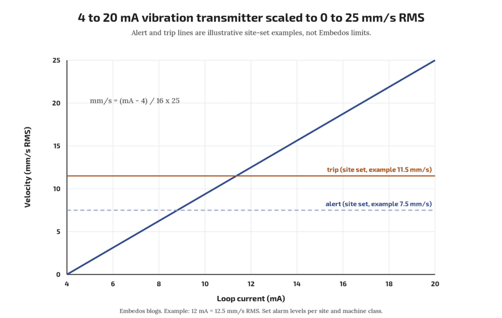
- Resolution where it matters. On a 0-25 mm/s range, 1 mm/s is 0.64 mA (16 mA ÷ 25). Healthy machines often run at a few mm/s, so a wider range such as 0-50 mm/s halves the current change per mm/s and makes small trends harder to see on a 12-bit input.
- Headroom above trip. Set alert and trip levels by evaluating against ISO 20816-3 zone boundaries for the machine group and foundation (ISO 20816-3). A 25 mm/s top leaves room above trip so the signal does not saturate during a fault.
Pick 0-50 mm/s or wider only for machines that run rough by design (some crushers, vibrating screens) where the maker states higher normal levels.
Scaling: velocity = (mA − 4) ÷ 16 × 25. At 8 mA, velocity = 4 ÷ 16 × 25 = 6.25 mm/s. Check your own with the 4-20 mA loop scaling calculator.
What should the input read when the wire breaks?
Below 4 mA, often near 0 mA. Set the receiver to flag a current below the NE 43 failure range (about 3.6 mA on most transmitters; check the manual) as a fault, in line with NAMUR NE 43 (NAMUR). Check whether your transmitter supports NE 43 signalling.
Frequency band
The broadband measurement band depends on machine speed per ISO 20816; read the band for your machine from the relevant part (ISO 20816-1).
Buyer checks:
- Does the datasheet state the band and does it suit your machine speed per ISO 20816? If not, ask.
- Slow machines: a fan at 300 rpm runs at 5 Hz. A transmitter whose lower cut-off sits near or above 5 Hz will miss most of its 1× vibration. Choose a transmitter with a lower cut-off well below running speed.
- Bearing defects: early rolling bearing faults show at higher frequencies and often in acceleration, not velocity. A 0-25 mm/s velocity transmitter is a general health trend, not a bearing diagnostic tool.
Can one 4-20 mA transmitter catch bearing faults early?
Not reliably. It gives overall velocity. For early bearing faults, look at acceleration or envelope values, usually from an RS-485 or portable analyser. See ENQ-007 for the trade-off.
Mounting
Mounting changes the reading more than most spec items.
- Location: on the bearing housing, close to the load zone, in the direction you want to watch (horizontal on most horizontal machines, since stiffness is usually lowest there).
- Method: a stud on a spot-faced flat surface gives the best frequency response. Adhesive mounting pads are a common second choice. Magnets are for surveys. Vendor application notes show how the usable upper frequency drops as mounting gets less rigid; check the accelerometer maker’s mounting manual for the response of each method.
- Thread: confirm thread size (often 1/4-28 UNF or M8) and whether an adaptor is supplied.
- Cable: armoured or screened twisted pair, screen grounded at one end per your plant practice. On VFD-driven motors keep the run away from motor power cables.
- Enclosure: state the IP rating needed. Degrees of protection are defined in IEC 60529 (IEC webstore). For hosed-down areas ask for IP66 or IP67 and check the cable gland too.
- Hazardous areas: if the motor is in a classified zone, you need a certified transmitter and the right barrier. Do not substitute.
Download the Free “Vibration Transmitter 4-20mA 0-25 mm/s Checklist”
Enter your email and the form emails you the copy link to the Google Sheet.
Alarm limits: how to frame them
ISO 20816 evaluates vibration in two ways: absolute magnitude against zones, and change from a known baseline. Use both.
- Classify the machine by type, power and foundation (rigid or flexible) as the relevant ISO 20816 part requires.
- Read the zone boundaries from that part for your class. Zone A is new machines, B is acceptable for long-term running, C is limited running, D is damaging.
- Set alert near the B/C boundary, or at baseline plus an agreed step if the machine normally runs well below it.
- Set trip no higher than the C/D boundary, and only if your protection philosophy allows a trip from this signal.
- Add a delay of a few seconds to ride through start-up transients.
Alert and trip values are site decisions. Write down which ISO part and table you used so the next engineer can check it.
Should a vibration transmitter trip the motor directly?
Some plants wire it to a PLC trip; others alarm only. Follow your protection philosophy and get it reviewed. Never rely on a polled network value as the only trip path without review.
Spec sheet checklist
| Item | What to write |
|---|---|
| Measured quantity | RMS velocity, mm/s |
| Range | 0-25 mm/s (state if different, with reason) |
| Output | 4-20 mA, 2-wire loop powered, NE 43 fault signalling if available |
| Frequency band | Per machine speed (ISO 20816); lower cut-off for slow machines |
| Supply | e.g. 24 V DC nominal; check minimum loop voltage with your input load |
| Mounting | Stud, thread size, spot-face required |
| Enclosure | IP rating per IEC 60529; cable entry type |
| Temperature | Ambient and surface temperature of the bearing housing |
| Approvals | Hazardous area certification if needed |
| Documents | Datasheet, calibration certificate, mounting guide |
Where the data goes
The 4-20 mA loop lands on a PLC analog input or a gateway. From there it can be trended and alarmed. Embedos has interfaced third-party vibration sensors with Embedos Edge, our platform of products, solutions, dashboards, insights and services.
A vibration monitoring software case records a historical EmView-named desktop deployment that logged spindle vibration over OPC UA; that page is a case note, not the current EmView product definition.
Today, readings can be shown on EmView monitoring screens (sign in at emcommandview.embedos.io). The transmitter itself is chosen from your preferred instrument vendor.
FAQ
Why 0-25 mm/s and not 0-50 mm/s?
Better resolution at normal running levels, while still above typical trip levels for general machines. Use wider ranges only where the maker states higher normal vibration.
RMS or peak velocity?
RMS, to compare against ISO 20816 framing. Peak is about 1.41 × RMS for a pure sine.
What frequency band do I need?
The band depends on machine speed per ISO 20816; slow machines need a lower cut-off. Confirm against the ISO part you use.
Stud or magnet mounting?
Stud for permanent installs. Magnets shift and reduce high-frequency response.
4-20 mA or RS-485?
4-20 mA for one value per point into existing analog I/O; RS-485 for multiple values per sensor on one cable.
Next step
Send your motor list (power, speed, foundation type) and we will help you frame the transmitter spec and alarm limits.
Email: team@embedos.io
Help Us Help You Leverage The Power Of Industrial Automation & Industrial IoT – IIoT.