
What is an OEE monitoring system?
A setup that collects run state, part counts and reject counts from machines, and calculates availability, performance and quality, and their product, Overall Equipment Effectiveness (OEE)
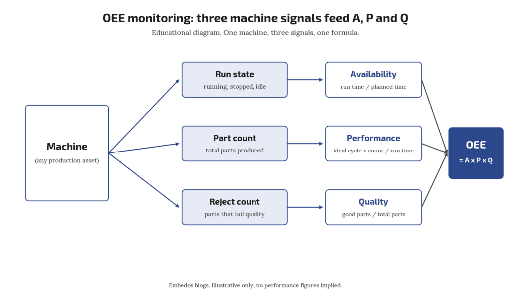
An OEE monitoring system needs three groups of signals from each machine: a reliable running or stopped state (for availability), a part or cycle count against an agreed ideal cycle time (for performance), and a good or reject count (for quality).
OEE is availability × performance × quality.
On mixed-vintage shop floors the hard part is not the formula, it is getting a trustworthy run signal and part count from machines that were never built to report them.
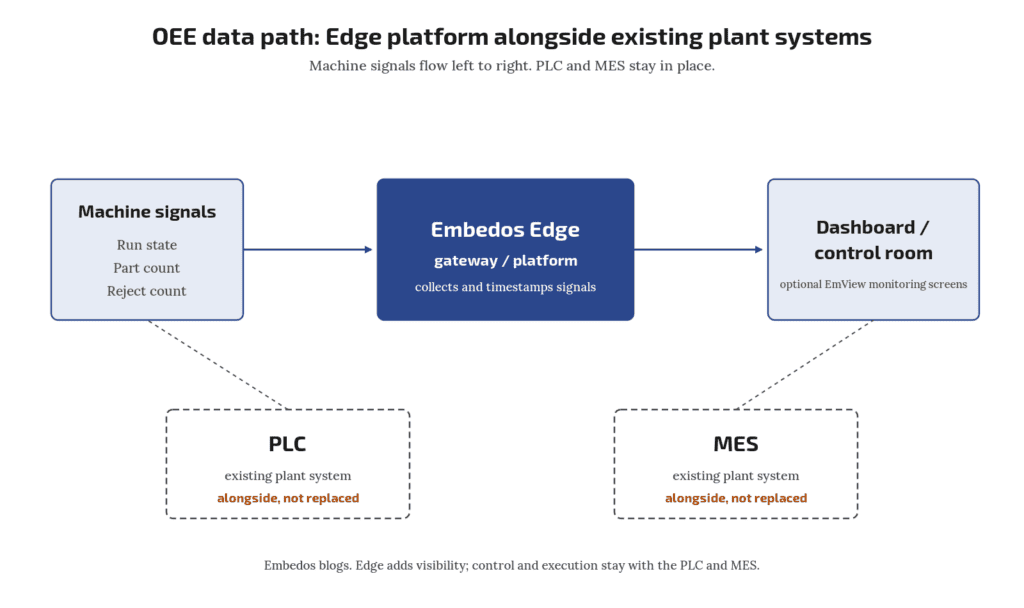
A logging layer or edge gateway can collect those signals and send them to a dashboard or control room; it does not replace your MES, SCADA or PLC.
Who this is for: production, maintenance and automation engineers who have been asked to “show OEE” for a line of presses, CNCs, moulding machines or packing machines of different ages and makes.
Is there a standard definition of Overall Equipment Effectiveness (OEE) ?
ISO 22400-2 defines Overall Equipment Effectiveness (OEE) among its manufacturing KPIs. Plants still need local rules for planned time and rework.
Why this question keeps coming up
A recent enquiry from an instrumentation firm asked a common thing: their client wanted OEE on a set of older machines and wanted to know what had to be wired before any software discussion. That is the right order. Decide the signals first; the dashboard comes later.
OEE in one formula
OEE is defined as a key performance indicator in ISO 22400-2, the standard for KPIs in manufacturing operations management (ISO 22400-2:2014). In plain terms:
- Availability = actual run time ÷ planned production time.
- Performance = (ideal cycle time × total count) ÷ run time.
- Quality = good count ÷ total count.
- OEE = availability × performance × quality.
Worked example (illustrative numbers only): a shift has 480 min planned time. The machine runs 420 min, so availability = 0.875. Ideal cycle time is 30 s and it makes 760 parts, so performance = (0.5 min × 760) ÷ 420 = 0.905. 740 parts are good, so quality = 0.974. OEE = 0.875 × 0.905 × 0.974 ≈ 0.77.
Each factor depends on a different physical signal. If one signal is wrong, the OEE number is wrong in a way the formula will not show you. If you want the reasoning for measuring this before buying an MES, read our post on an OEE baseline before MES.
How do I record downtime reasons?
Operator entry on an HMI, button panel or tablet, with a short reason list agreed with production.
Availability: get the run signal right
Availability needs two things: when the machine is running and what counts as planned time.
Run signal options, roughly in order of preference:
- A PLC or CNC status bit (cycle active, auto mode, spindle on) read over the machine’s own interface, if one exists. Check the controller vendor’s documentation for which bit means “producing” and not just “powered”.
- A spare contact or output from the machine’s control circuit, such as a motor contactor auxiliary contact or a cycle-start relay, wired to a digital input.
- Motor current via a current transformer and a threshold. This works on machines with no spare contacts, but you must pick a threshold that separates idle from cutting or pressing. Idling hydraulic pumps can draw a lot of current while nothing is produced.
- Spindle or shaft speed from a proximity sensor on a rotating part.
Planned time is a business rule, not a sensor. Agree shift times, breaks and planned maintenance with production before you start, or availability will be argued over forever.
Downtime reasons (no material, tool change, breakdown, waiting for QC) usually come from an operator entry: a button panel, an HMI screen or a tablet. Keep the list short; ten reasons that people actually press beat forty that nobody uses.
Is "machine powered on" good enough as a run signal?
Usually no. A machine can be powered and idle for hours. Use a signal tied to production, such as cycle active, a stroke, or a load threshold on motor current.
Performance: count cycles, not guesses
Performance needs a total count and an ideal cycle time for each product or die.
- Count source: a stroke or cycle pulse from the controller, a proximity sensor on a moving part, or a photoelectric sensor at the outfeed. For high speed counts, check that the input’s maximum count frequency covers your fastest cycle. Inductive proximity switches are covered in IEC 60947-5-2:2019.
- Multi-cavity or multi-up tools: one stroke can make several parts. Store parts per cycle with the job, not as a fixed machine setting.
- Ideal cycle time: take it from the process engineer’s standard, not from last month’s average. If you use an average, poor performance becomes the baseline.
Micro-stops (stops of a few seconds) are often where performance loss hides.
A count signal logged with a timestamp lets you see them later without any extra sensor.
Where do I get ideal cycle time for old machines?
From the process sheet or the machine nameplate rating for that job. If neither exists, run a clean trial with an experienced operator and record the best sustained rate, then get production to agree it in writing.
Quality: the signal most plants skip
Quality = good ÷ total. Sources:
- Automatic reject: a reject gate, a checkweigher or vision system output, wired as a second count.
- Operator entry: rejects entered per shift or per lot on an HMI or tablet.
- Rework: decide up front whether reworked parts count as good. ISO 22400-2 treats quality ratios in terms of good quantity, so write the rule down.
If you only have end-of-shift reject entries, quality will be daily rather than live. That is fine for a first baseline.
Download the Free “OEE Monitoring Signal Checklist”
Enter your email and the form emails you the copy link to the Google Sheet.
Can I measure OEE on machines with no PLC?
Yes, using external signals: contactor auxiliary contacts or a current threshold for run state, and proximity or photoelectric sensors for counts.
Signal checklist for mixed-vintage machines
Use this per machine. It doubles as the downloadable checklist (lead magnet: oee-monitoring-signal-checklist).
| Item | Newer machine (has controller interface) | Older machine (relay logic or none) |
|---|---|---|
| Run state | Controller status bit over its protocol | Contactor aux contact or CT current threshold |
| Cycle count | Controller counter or cycle-complete bit | Proximity or photoelectric sensor on stroke or outfeed |
| Parts per cycle | Job recipe | Manual entry per job |
| Reject count | Reject station output | Operator entry |
| Downtime reason | HMI screen | Button panel or tablet |
| Timestamp source | Gateway or server clock synced to NTP | Same |
Points to check on site:
- Is there a spare contact, or do you need an interposing relay so you never load the machine’s control circuit?
- What voltage is the signal: 24 V DC, 110 V AC, 230 V AC? Use the right input or an isolating relay.
- Can the machine’s own controller be read without affecting its program? Ask the OEM before connecting anything to a running controller.
- Who owns the clock? Every count and stop should carry one consistent timestamp. NTP is defined in RFC 5905 (IETF).
Do I need to open the machine's PLC program?
Not always. Many retrofits use only external signals (contacts, CTs, proximity sensors) so the OEM program is untouched. That keeps warranty and validation discussions simple.
Where an edge gateway fits, and where it does not
An edge gateway or logger sits between the machine signals and the dashboard. Its jobs are narrow:
- read digital inputs, counters and analog signals, or poll a controller over Modbus or similar;
- timestamp and buffer data if the network drops;
- send data to a server, cloud or control room screen.
It does not run your machine, replace the PLC, or replace an MES that handles work orders, genealogy and scheduling. For retrofit wiring and protocol options on older machines, see retrofitting legacy machines with OPC UA and Modbus. For Modbus itself, the protocol specifications are published by the Modbus Organization.
Embedos Edge is our platform of products, solutions, dashboards, insights and services. On an OEE project it captures machine and sensor data and sends it to the cloud or a control room, with homepage widgets and smart alerts for stoppages. EmView monitoring screens can show the same data in a control room (sign in at emcommandview.embedos.io; )
It sits alongside your PLC, SCADA and MES; it is not a replacement for any of them. Any OEE figure it shows is only as good as the run, count and reject signals you wire into it.
Common mistakes
- Counting from the wrong point. A sensor before a reject gate counts total; one after it counts good. Know which you have.
- Mixing ideal and average cycle times across products.
- No agreed planned time, so availability changes depending on who reads the report.
- Trusting a single number. Always look at A, P and Q separately. An OEE of 0.77 tells you little; availability of 0.875 with performance of 0.905 tells you where to look.
- Starting with too many machines. Wire two or three, check the counts against the shift register for a week, then roll out.
Validate before you report
For the first week, compare logged counts with the operator’s shift register and logged stops with maintenance records. Differences point to a bad signal choice, not bad operators. Fix the signal, then publish numbers.
Does an OEE system replace MES or SCADA?
No. It gives you measured losses. MES handles orders and genealogy; SCADA handles supervisory control. A gateway feeds data to them or alongside them.
Next step! Send us a Mail
Send your machine list, ages and what signals each one already has, and we will help you plan the wiring.
Help Us Help You Leverage The Power Of Industrial Automation & Industrial IoT - IIoT.