
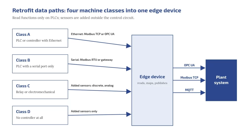
You can retrofit legacy machines without touching their control logic. Classify each machine first: PLC with Ethernet, PLC with serial only, relay or electromechanical, or no controller at all. Then read the PLC over Modbus or OPC UA using read functions only, or add sensors outside the control circuit where there is no usable PLC. Publish everything upwards through open protocols, and use OPC UA where you need structure and security that plain Modbus does not give.
Who this is for:
Plant heads deciding between retrofit and replacement, and the maintenance and automation engineers who have to connect mixed-age machines and older PLCs.

What you'll be able to do after reading:
Classify your machines, choose Modbus, OPC UA or added sensors per machine, map Modbus registers to OPC UA variables, plan a first retrofit that cannot write to a PLC, and judge when to replace instead.
Why retrofit before you replace?
A machine that still makes good parts usually has years of mechanical life left even when its controls are old. Retrofitting adds data without changing how the machine runs, so it costs a fraction of a replacement in money and downtime and can start on one machine. Replacement makes sense when spares, support or safety, not data, are the problem; the questions for that decision are further down.
Step 1: classify every machine
| Class | What it has | Typical data path |
|---|---|---|
| A | PLC or controller with Ethernet | Modbus TCP, or the controller’s OPC UA server if it has one |
| B | PLC with a serial port only | Modbus RTU if the PLC can act as a Modbus slave, or a protocol gateway |
| C | Relay or electromechanical controls | Discrete and analog signals from added sensors |
| D | No controller at all | Added sensors only |
Walk the floor with this table: note panel space, nameplates, existing ports and spare terminals for each machine. A closed controller with no documentation goes into class C or D, even if it has a port.
Step 2: choose the data path per class
| Point | Added sensors (current, 4 to 20 mA, RTD, counts) | Reading the PLC (Modbus or OPC UA) |
|---|---|---|
| Touches the control system | No, if mounted outside the control circuit | A connection to its communication port, configured to use read functions only |
| Signals available | Only what you measure | Everything the PLC knows, if documented |
| Downtime reasons | Operators tag them | Alarm and fault codes, if mapped |
| Dependence on the machine builder | Low | Higher: you need the memory map or tag list |
| Best for | Classes C and D, quick uniform run and idle data | Classes A and B with documented controllers |
How do you connect a PLC to the internet or cloud?
Not directly. CISA’s first OT mitigation is to remove OT connections to the public internet. Connect the PLC to an edge device on the OT network; the edge device reads it and sends data onward over a controlled, outbound route.
Can we use the machine's existing sensors?
Sometimes, through the PLC. Splitting an existing analog signal can disturb the control loop, so add a separate sensor when in doubt.
Worked example: scaling a 4 to 20 mA signal
A pressure transmitter on a 0 to 10 bar range, a 150 ohm sense resistor, and a 12-bit ADC with a 3.3 V reference. The loop reads 12.6 mA. These numbers match the free tool to scale 4-20 mA signals from relay-era machines.
- Sense voltage = 12.6 mA × 150 ohm = 1.890 V.
- ADC counts = (1.890 ÷ 3.3) × 4095 = 2345.
- Process value = 0 + ((12.6 − 4) ÷ 16) × 10 = 5.375 bar.
- At 4 mA the ADC reads 745 counts, at 20 mA 3723 counts, so resolution is about 0.0034 bar per count.
- At or below 3.6 mA, or at or above 21 mA, NAMUR NE 43 treats the signal as a failure, for example a transmitter fault or a broken wire, so alarm on it instead of showing 0 bar. Readings from 3.8 to 4.0 mA and 20.0 to 20.5 mA are still valid, just under or over range. NE 43 itself is a paid NAMUR document; Beckhoff’s documentation summarises its limits.
A 250 ohm resistor puts 20 mA at 5 V, which clips a 3.3 V ADC. For ovens, dryers and moulds, check temperature readings with the RTD PT100 and PT1000 calculator, including the error a 2-wire RTD adds through its leads.
What does OPC UA add over Modbus?
| Point | Modbus | OPC UA |
|---|---|---|
| Data model | Numbered registers and coils; meaning lives in a separate document | Named, typed nodes in an information model that clients can browse, as the OPC UA overview describes |
| Machine description | None | Companion specifications such as OPC 40001-1 Machinery: identification, state, counters |
| Security | None in plain Modbus; Modbus/TCP Security adds TLS on port 802 | Built in: application authentication, signing and encryption, per the OPC UA security model |
| Typical role in a retrofit | Reading old devices | Publishing structured data upwards |
OPC UA is an open, royalty-free set of standards from the OPC Foundation, as the Machinery specification notes, and the full specifications are free to read online. So the usual answer to “OPC UA vs Modbus” in a retrofit is both: Modbus at the bottom, OPC UA at the top. The OPC Foundation also publishes an open-source edge application, UA Edge Translator, that translates other protocols into OPC UA.
Download the Free “Legacy Machine Retrofit Playbook (Checklist)”!
What is OPC UA used for?
Exchanging industrial data between machines, controllers and plant or business systems, with an information model and built-in security.
OPC UA vs Modbus: which should I use?
Modbus is often all an old device speaks. OPC UA is better for publishing structured, secured data upwards. Many retrofits use both.
Is OPC UA secure, and is it free?
Its security model includes authentication, signing and encryption. The standards are royalty free and readable online, and the OPC Foundation publishes open-source code.
Modbus to OPC UA gateways: mapping registers to variables
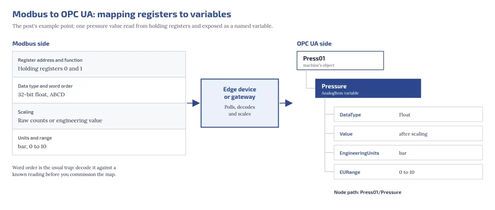
An edge device or gateway polls Modbus and exposes each value as an OPC UA variable. For every point, define:
| Modbus side | OPC UA side | Example |
|---|---|---|
| Register address and function | Node name under the machine’s object | Holding registers 0 and 1 → Press01/Pressure |
| Data type and word order | DataType | 32-bit float, ABCD → Float |
| Scaling | Value after scaling | Raw counts or engineering value |
| Units and range | EngineeringUnits and EURange of an AnalogItem | bar, 0 to 10 |
Wikipedia’s OPC Unified Architecture article is useful further reading on OPC UA itself. Word order is the usual trap: decode Modbus float word order against a known reading before you commission the map. For the transport underneath, see Modbus RTU vs Modbus TCP.
How does a Modbus to OPC UA gateway work?
It polls Modbus registers, decodes and scales them, and exposes each as a named OPC UA variable with type and units.
Start with read functions only
Modbus has no read-only mode, and OPC UA has none by default: any client that reaches the port can send write function codes (05, 06, 15 and 16 in the Modbus application protocol specification) unless something blocks them. So “read-only” is a configuration the integrator must enforce: disable or block write function codes in the edge device or gateway, and do not enable writes until change control is in place. NIST SP 800-82 Rev. 3 and CISA’s OT mitigations also call for segmenting IT and OT networks, changing default passwords and securing remote access.
Do we need OEM permission, and does it affect the warranty?
- Sensors outside the control circuit do not change how the machine runs. Still inform the OEM while under warranty.
- A connection to an existing communication port that is configured to use only read functions does not change the PLC program. Disable or block write function codes in the edge device or gateway, but the OEM may still need to tell you the settings and memory map.
- Any change to the PLC program, safety circuits or control wiring needs written OEM approval while under warranty. Do not do it for monitoring. Check your contract in every case.
What happens to production during the install?
- Survey while the machine runs.
- Prepare and test the edge device and configuration off the machine.
- Install sensors and cabling during an existing planned stop.
- Connect to the PLC with write function codes blocked at the edge device, and confirm the HMI and control behave as before.
- Run in parallel with manual logs until the numbers agree.
Should a retrofit start read-only?
Yes, in practice: block write function codes at the edge device or gateway, because neither Modbus nor OPC UA is read-only by default.

A pilot plan: one line, a fixed window, clear measures
- Pick one line, including its constraint machine.
- Agree the window in advance and do not move it.
- Measure run state, part counts, downtime with reasons, and one or two process values that explain quality.
- Compare against manual logs, then use the data for an OEE baseline.
- Decide the next line only once the first line’s numbers are trusted.
How many signals per machine should we start with?
Run state and part count. Add process values only where they explain quality or downtime.
Retrofit vs replace: questions for the plant head
- Are spares for the controller still available, and from whom?
- Does the OEM still support the controller and its software?
- Is the problem missing data, or unreliable control and safety?
- How much downtime would a replacement need, and when could the plant afford it?
- Will a retrofit now still be useful if the controller is replaced later?
Will a retrofit lock us into one vendor?
It does not have to. Put these in the order: data published over open protocols such as OPC UA, Modbus TCP or MQTT; raw data exportable in an open format such as CSV without a licence fee; full tag documentation; standard signals (4 to 20 mA, RTD, 24 V digital); and configuration backups handed to the plant.
Who should own the retrofit?
Maintenance or automation engineering for the hardware, with production agreeing what the data must answer.
Where does Embedos fit?
The Embedos Edge IoT gateway page lists Modbus RTU, Modbus TCP, CAN bus and OPC UA among supported protocols, and MQTT, HTTP and HTTPS for sending data onward. Our page on connecting PLCs and controllers describes how we work with automation engineers. For a new plant, put connectivity in the tenders instead, with the greenfield plant digital readiness checklist.
For engineers: check your loop scaling with the free 4 to 20 mA loop scaling calculator and your temperature readings with the RTD PT100 and PT1000 calculator.
Next step
Logging these sensors across the plant? Embedos Edge takes analog and digital I/O. Book a 20 min commissioning call.
Connecting this machine to your plant system? We build OPC UA links end to end. Email team@embedos.io about OPC UA integration.